

End stile
End stile
Lock or
Intermediate
section
#1Center
hinge(s)
#1 Graduated end hinge
#1 Graduated end hinge
Dimples
#1Center
hinge(s)
#1 Graduated
end hinge
Lower
hinge leaf
1/4”-20 x 7/8”
Self drilling
screws
Short
stem
track
roller
Stru
t
1/4”-20 x 7/8”
Self drilling screws
Strut
clips
Stru
t
Lower
hinge
leaf
Strut
clips
Strut
#1 Graduated
end hinges
Long stem
track roller
End stile
End stile
#1Center
hinge(s)
#1 Graduated end hinges
#1 Graduated end hinges
1/4”-20 x 7/8”
Self drilling screws
Dimples
Lock or
Intermediate
section
Strut
#1Center
hinge(s)
Lower
hinge leaf
1/4”-20 x 7/8”
Self drilling
screws
Strut
clips
Stru
t
Strut
clips
Strut
Lower
hinge leafs
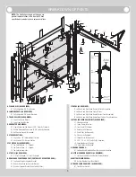
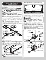
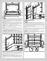
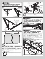
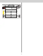
NOTE:
If a strut is required to be installed on a section with windows in it, half center hinge(s)
(if included) may need to be used instead of the typical center hinge(s).
Lower hinge leaf
1/4”-20 x 7/8”
Self drilling
screws
Strut
clips
Strut
Half center
hinge
Dimples
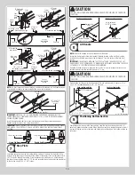
IMPORTANT:
ONCE THE 1/4” - 20 SELF DRILLING SCREWS ARE SNUG AGAINST THE
LOWER HINGE LEAFS, TIGHTEN AN ADDITIONAL 1/4 TO 1/2 TURN TO RECEIVE MAXIMUM
DESIGN HOLDING POWER.
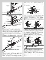
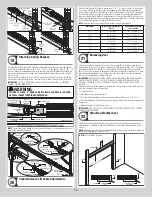
Insert the appropriate stem track roller into the hinge tube of the graduated end hinges.
Repeat the same process for all remaining sections.
Short stem track roller
Long stem track roller
Single End Hinge
Double End Hinge
IMPORTANT:
WHEN PLACING STEM TRACK ROLLERS INTO THE #2 GRADUATED END HINGES
AND HIGHER, THE STEM TRACK ROLLER GOES INTO HINGE TUBE FURTHEST AWAY FROM
SECTION.
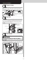
Step Plate
7
Locate the center most center stile on the bottom section of the door. On the inside of the
door and using the pre-punched holes at the bottom of the center stile as a template, drill (2)
7/32” dia. holes through the section. Using the previously drilled holes as a guide, enlarge
the holes from outside the door to 7/16” dia. and assemble the outside and inside step plates
to the section using (2) #8 x 1-5/8” screws.
CAUTION
DO NOT DRILL THROUGH OR ENLARGE HOLES ON THE INSIDE OF THE DOOR
SECTION.
Inside step plate
Bottom section inside
Pre-punched
holes
(2) #8 x 1-5/8” screws
8” Max.
mounting
height
Outside step plate
Bottom section outside
Holes enlarged
to 7/16” diameter
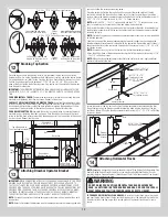
Lift Handle
8
NOTE:
Doors with a Keyed lock do not require this lift handle.
Locate the inside center stile or the desired lift handle location on the lock (2nd) section
of the door. Position the lower hole in the lift handle 4” from the bottom of the lock (2nd)
section.
IMPORTANT:
THE DISTANCE BETWEEN THE STEP PLATE AND THE MIDDLE OF THE LIFT
HANDLE MUST BE 20” MINIMUM TO 30” MAXIMUM. IF NECESSARY REPOSITION THE UPPER
LIFT HANDLE TO STAY WITHIN THE REQUIRED DIMENSION.
Using the lift handle holes as a template, drill (2) 9/32” dia. holes through the lock section.
Enlarge the holes from the outside the door to 1/2” dia.
CAUTION
DO NOT DRILL THROUGH OR ENLARGE HOLES ON THE INSIDE OF THE DOOR
SECTION.
Assemble the outside and inside lift handles to the lock section using (2) spacers, (2) 1/4” -
20 x 2-1/2” carriage bolts and (2) 1/4” - 20 hex nuts.
(2) Spacers
1/2” Diameter holes
(2) 1/4” x 2-1/2” Carriage bolts
Lift handle
4”
Lift handle
(2) 1/4”-20 hex nuts
Lock section outside
Lock section inside
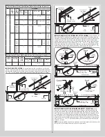
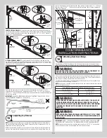
Positioning Bottom Section
9
Center the bottom section in the door opening. Level the section using wooden shims (if
necessary) under the bottom section. When the bottom section is leveled, temporarily hold it
in place by driving a nail into the jamb and bending it over the edge of the bottom section on
both sides.
10