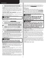


WARNING
WARNING
Lift handles/gripping points are required
on this door, located as spelled out in the
installation instructions, even if the door
is motor operated.
Failure to install and use these lift handles/
gripping points on this door can result in
serious injury to fingers and/or hands, if
placed in the opening between sections,
when the door is operated manually.
The adjacent bottom corner bracket and
all cable retention features including
milford pins, cotter pins, & clevis pins are
under HIGH SPRING TENSION.
Adjustments and repairs must only be
made by a trained door systems
technician, using proper tools and
instructions.
DO NOT REMOVE, COVER OR PAINT OVER
THIS LABEL. PRODUCT USER SHOULD
INSPECT THIS LABEL PERIODICALLY FOR
LEGIBILITY AND SHOULD ORDER A
REPLACEMENT FROM THE DOOR
MANUFACTURER AS NEEDED.
325304 REV3 06/26/12
© Copyright 2012,
Overhead Door Corporation
WARNING
WARNING
Lift handles/gripping points are required
on this door, located as spelled out in the
installation instructions, even if the door
is motor operated.
Failure to install and use these lift handles/
gripping points on this door can result in
serious injury to fingers and/or hands, if
placed in the opening between sections,
when the door is operated manually.
The adjacent bottom corner bracket and
all cable retention features including
milford pins, cotter pins, & clevis pins are
under HIGH SPRING TENSION.
Adjustments and repairs must only be
made by a trained door systems
technician, using proper tools and
instructions.
DO NOT REMOVE, COVER OR PAINT OVER
THIS LABEL. PRODUCT USER SHOULD
INSPECT THIS LABEL PERIODICALLY FOR
LEGIBILITY AND SHOULD ORDER A
REPLACEMENT FROM THE DOOR
MANUFACTURER AS NEEDED.
325304 REV3 06/26/12
© Copyright 2012,
Overhead Door Corporation
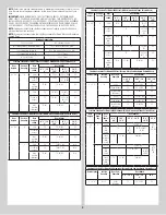
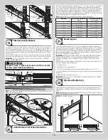
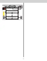
Spring Turns
Door Height
Spring Turns
(6’ - 0”)
14
(6’ - 3”)
14 - 1/2
(6’ - 5”)
15
(6’ - 6”)
15
(6’ - 8”)
15 - 1/2
(6’ - 9”)
15 - 1/2
(7’ - 0”)
16
(7’ - 3”)
16 - 1/2
(7’ - 6”)
17
(7’ - 9”)
17 - 1/2
(8’ - 0”)
18
Number of Installed Spring Turns
300547 REV2 01/15/2010
Copyright 2010 Wayne Dalton, a
Division of Overhead Door Corp.
HIGH SPRING TENSION CAN CAUSE
SERIOUS INJURY OR DEATH.
DO NOT
adjust, repair or remove springs or parts to
which springs are connected, such as steel brack-
ets, cables, wood blocks, fasteners or other parts of
the counterbalance system.
Adjustments or repairs must
ONLY
be made by a
trained door systems technician using proper tools
and instructions.
DO NOT
remove, cover or paint over this tag. Prod-
uct user should inspect this tag periodically for
legibility and should order a replacement tag from
the door manufacturer, as needed.
©Copyright 2010 Overhead Door Corporation
102081 REV2 06/24/2010
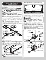
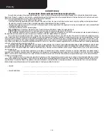
SAFETY INSTRUCTIONS
1.
Operate door ONLY when it is properly
adjusted and free of obstructions.
2.
If a door becomes hard to operate,
inoperative or is damaged, immediately
have necessary adjustments and/or repairs
made by a trained door system technician
using proper tools and instructions.
3.
DO NOT stand or walk under a moving door,
or permit anybody to stand or walk under
an electrically operated door.
4.
DO NOT place fingers or hands into open
section joints when closing a door. Use lift
handles/gripping points when operating
door manually.
5.
DO NOT permit children to operate garage
door or door controls.
6.
Due to constant extreme spring tension,
DO NOT attempt any adjustment, repair or
alteration to any part of the door,
especially to springs, spring brackets,
bottom corner brackets, red colored
fasteners, cables or supports. To avoid
possible severe or fatal injury, have any
such work performed by a trained door
system technician using proper tools and
instructions.
7.
On electrically operated doors, pull down
ropes must be removed and locks must be
removed or made inoperative in the open
(unlocked) position.
8.
Top section of door may need to be
reinforced when attaching an electric
opener. Check door and/or opener
manufacturer’s instructions.
9.
VISUALLY inspect door and hardware
monthly for worn and/or broken parts.
Check to ensure door operates freely.
10.
Test electric opener’s safety features
monthly, following opener manufacturer’s
instructions.
11.
NEVER hang tools, bicycles, hoses, clothing
or anything else from horizontal tracks.
Track systems are not intended or designed
to support such extra weight.
Place label at a readable height on door. DO NOT
remove, cover or paint over this label. Product
user should inspect this label periodically for
legibility and should order a replacement label
from the door manufacturer as needed.
324100 REV7 09/16/2013
Quality garage doors since 1954
Wayne Dalton
2501 S. State Hwy 121 Bus., Suite 200
Lewisville, TX 75067
For service, call (800) 827-3667
www.Wayne-Dalton.com
Copyright 2013 Wayne Dalton, a
Division of Overhead Door Corp.
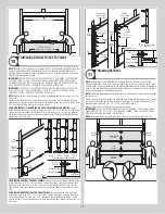
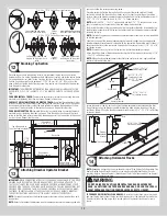
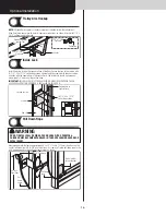
Residential warning label, The warning label will
either be on the right or the left end stile.
Bottom corner bracket warning labels
Torsion spring tag(s)
(one per spring)
TorqueMaster
®
Plus tag(s)
(one per spring)
18


