
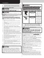
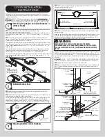
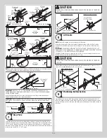
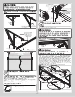


WARNING
FAILURE TO ASSEMBLE AND ATTACH REAR BACK HANGS PROPERLY
ACCORDING TO THE ABOVE INSTRUCTIONS MAY RESULT IN DOOR
FALLING WHEN RAISED, CAUSING SEVERE OR FATAL INJURY.
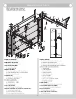
NOTE:
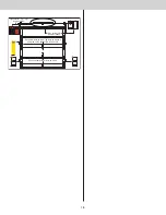
Perforated angle must be attached to sound framing members and
nails should not
be used
.
90°
(3) 5/16”
Bolts and nuts
(3) 5/16” Bolts and
(3) 5/16” nuts
Perforated
angle
5/16” Hex nut
5/16”-18 x 1-1/4”
Hex bolt
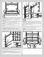
Perforated angle bolted
using (2) 5/16” x 1-5/8”
hex head lag screws to
ceiling member and
parallel to door
Horizontal track
NOTE:
Repeat the same
process for right hand side.
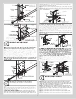
Horizontal tracks
Door edges
3/4” To 7/8”
3/4” To 7/8”
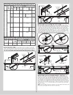
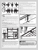
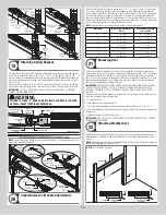
Attaching Front Cable Lift Sheaves
17
IF YOU HAVE 3” FRONT CABLE LIFT SHEAVE AND A 12” RADIUS HORIZONTAL TRACK:
Starting on the left hand side and using (1) 3/8” - 16 hex nut, secure the front cable lift
sheave to the 13/32” hole near the top of the flag angle, as shown.
IF YOU HAVE 3” OR 4” FRONT CABLE LIFT SHEAVE AND A 15” RADIUS HORIZONTAL
TRACK:
Starting on the left hand side and using (1) 3/8” - 16 hex nut, secure the front cable
lift sheave to the first 13/32” hole in the horizontal angle, as shown.
Repeat the same process for the right hand side.
Horizontal track angle
Horizontal track radius
Flag angle
3/8”-16
Hex nut
Horizontal
track angle
12” Radius horizontal
track with 3” front cable
lift sheave hole location
Horizontal track
15” Radius horizontal track
with 3” or 4” front cable lift
sheave hole location
or
12” Radius horizontal track
with 4” front cable lift
sheave hole location
3” or 4”
Front cable
lift sheave
Front cable lift sheave
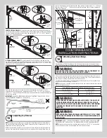
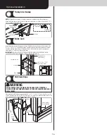
Attaching Extension Springs
18
Remove the locking pliers from the vertical tracks.
WARNING
WITH ASSISTANCE, RAISE THE DOOR SLOWLY INTO THE OPEN POSITION
MAKING SURE THE DOOR TRAVELS SMOOTHLY THROUGH THE TRACKS.
CLAMP LOCKING PLIERS TO THE BACK LEG OF BOTH HORIZONTAL
TRACKS, BELOW THE BOTTOM TRACK ROLLERS TO KEEP THE DOOR
FROM LOWERING.
Locking
pliers
NOTE:
This illustration shows the outside of the door
in the open position.
Bottom
section
Track
roller
WARNING
FAILURE TO INSTALL SPRING RESTRAINT CABLES CAN RESULT IN
SEVERE OR FATAL INJURY IN CASE OF SPRING BREAKAGE.
Position (1) 5/16” - 18 x 3-3/4” eye bolt and (1) 5/16” - 18 hex nut into the rear back hang,
6” to 8” above the horizontal track, as shown. Feed the spring safety cable through the rear
back hang and tie the special knot around the “room side” of the 3 hole clip, as shown.
Secure the eye bolt and 3 hole clip to the rear back hang using (1) 5/16” - 18 hex nut. Hook
one end of the extension spring onto the eye bolt. Feed the spring safety cable through the
rear extension spring loop and center of the extension spring then front spring loop, pull the
spring safety cable taut and tie the special knot around the “jamb side” of the 3 hole clip.
Attach the “jamb side” 3 hole clip to the jamb near the flag angle using (1) 5/16” x 1-5/8” lag
bolt. Repeat the same process for the other side.
IMPORTANT:
SPRING RESTRAINT CABLES MUST BE TAUT AND EQUALIZED.
5/16”-18 x 3-3/4”
Eye bolt
Horizontal
track
Extension
spring
Back
view
Front view
Spring restraint
cable
Spring
restraint cable
Loop
5/16” x 1-5/8”
Lag bolt
3 Hole
clip
Special
knot
3 Hole
clip
Rear
back
hang
Extension
spring
5/16”-18 x 3-3/4”
Eye bolt
Extension
spring
Spring
restraint
cable
14


