


3/8”-16
Hex nut
3/8”-16 x
3/4” Truss
head bolt
Quick
Install
tab
Key
slot
Quick
Install
tab in
place
Level
Horizontal track angle
Flag
angle
upper
slot
Flag
angle
Horizontal
track
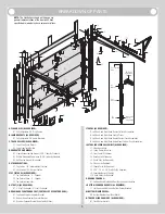
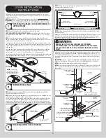
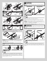
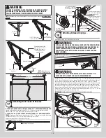
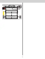
FOR OTHER FLAG ANGLES:
To install horizontal track, place the curved end over the top
track roller of the top section. Align the bottom of the horizontal track with the top of the verti-
cal track. Tighten the horizontal track to the flag angle with (2) 1/4” - 20 x 9/16” track bolts
and (2) 1/4” - 20 flange hex nuts.
3/8”-16
Hex nut
Horizontal
track angle
3/8”-16 x
3/4” Truss
head bolt
1/4”-20 x
9/16”
Track bolts
1/4”-20
Flange hex
nuts
Horizontal
track
Flag angle
upper slot
Level
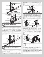
IF YOU HAVE ANGLE MOUNT:
To install horizontal track, place the curved end over the
top track roller of the top section. Align the bottom of the horizontal track with the top of the
vertical track. Tighten the horizontal track to the angle mount with (2) 1/4” - 20 x 9/16” track
bolts and (2) 1/4” - 20 flange hex nuts.
3/8”-16
Hex nut
Angle
mount
3/8”-16 x
3/4” Truss
head bolt
1/4”-20 x
9/16”
Track bolts
1/4”-20
Flange
hex nuts
Horizontal
track
Upper slot
Level
Vertical
track
Horizontal
track angle
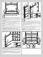
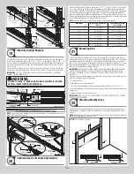
Next level the horizontal track assembly and bolt the horizontal track angle to the first
encountered slot in the flag angle / angle mount using (1) 3/8” - 16 x 3/4” truss head bolt
and (1) 3/8” - 16 hex nut. Repeat for other side. Remove nail that was temporally holding the
top section in position.
IMPORTANT:
FAILURE TO REMOVE NAIL BEFORE ATTEMPTING TO RAISE DOOR COULD
CAUSE PERMANENT DAMAGE TO TOP SECTION.
Horizontal
track
Level
Level
Horizontal
track angle
Horizontal
track angle
Horizontal
track
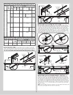
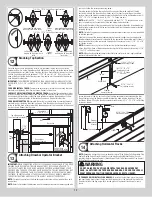
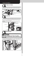
Adjusting Top Fixtures
15
NOTE:
Depending on your door, you may have Top Fixture Bases and Top Fixture Slides or
you may have Top Fixture Assemblies. Refer to Package Contents / Breakdown of Parts, to
determine which Top Fixtures you have.
With horizontal tracks installed, you can now adjust the top fixtures. Vertically align the top
section of the door with the lower sections. Once aligned, position the top fixture slide, out
against the horizontal track. Maintaining the slide’s position, tighten the (2) 1/4” - 20 flange
hex nuts or the (1) 5/16” - 18 hex nut to secure the top fixture slide to the top fixture base.
Repeat for other side.
Top fixture slide
Tighten the (2)
1/4”- 20 flange
hex nuts
Horizontal
track
Track roller
Top section
Intermediate
section
Top
section
Top
section
Top fixture
slide
Horizontal
track
Track roller
Top
section
Intermediate
section
Top
section
Top
section
Tighten the
5/16”-18
hex nut
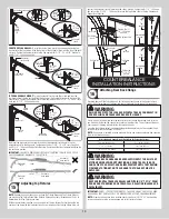
COUNTERBALANCE
INSTALLATION INSTRUCTIONS
Attaching Rear Back Hangs
16
Raise the door until the top section and half of the next section are in the horizontal track
radius. Do not raise door any further since rear of horizontal tracks are not yet supported.
WARNING
RAISING DOOR INTO THE LOOSE HORIZONTAL TRACKS CAN RESULT IN
DOOR FALLING AND CAUSE SEVERE OR FATAL INJURY.
Clamp a pair of locking pliers onto the vertical tracks just above the second track roller on
one side, and just below the second track roller on the other side. This will prevent the door
from raising or lowering while installing the rear back hangs.
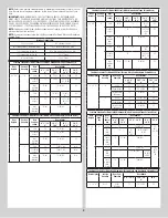
Using the chart below, select the appropriate perforated angle (may not be supplied). Fabri-
cate and install rear back hangs, as shown.
NOTE:
If an opener is installed, position horizontal tracks one hole above level when securing
them to the rear back hangs.
Perforated Angle Gauge Weight Limitations For Extension Springs:
Perforated Angle Gauge
Door Balance Weight
2” x 2” x 12 Gauge
Less Than 400 lbs.
1-1/4” x 1-1/4” x 13 Gauge
Less Than 175 lbs.
WARNING
MAKE SURE BACK HANGS ARE BRACED SUFFICIENTLY TO RESIST ANY
MOTION DURING SPRING APPLICATION AND DOOR TRAVEL. IF BACK
HANGS PIVOT OR DEFLECT, ADD REINFORCEMENT UNTIL THEY REMAIN
FIRM AND STATIONARY. ANY BACK HANG THAT HAS BENT MUST BE
REPLACED.
WARNING
KEEP HORIZONTAL TRACKS PARALLEL AND WITHIN 3/4” TO 7/8” FROM
DOOR EDGE, OTHERWISE DOOR COULD FALL, RESULTING IN SEVERE OR
FATAL INJURY.
IMPORTANT:
DO NOT SUPPORT THE WEIGHT OF THE DOOR ON ANY PART OF THE REAR
BACK HANGS THAT CANTILEVERS 4” OR MORE BEYOND A SOUND FRAMING MEMBER.
NOTE:
If rear back hangs are to be installed over drywall, use (2) 5/16” x 2” hex head lag
screws and make sure lag screws engage into solid structural lumber.
13


