
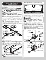
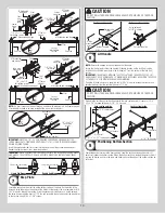
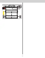


End cap
Roller spacer
Counterbalance
cable loop
1/4”-20 x 11/16”
Self drilling screws
Bottom section
Short stem track roller
Milford pin
Bottom corner
bracket
Counterbalance
lift cable
Bottom weather
seal
(3) 1/4”-20 x 11/16” Self
drilling screws (RED HEAD )
End cap
Counterbalance
lift cable
Bottom weather
seal
Bottom
section
Bottom corner
bracket
1/4”-20 x 11/16”
Self drilling screws
Counterbalance
cable loop
Cotter pin (attached into
place from opposite
side of bottom bracket)
Clevis pin (inserted through
cotter pin and bent into place)
Washer
(3) 1/4”-20 x 11/16” Self
drilling screws (RED HEAD )
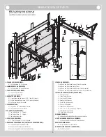
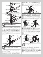
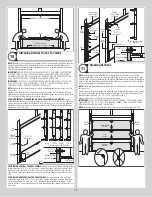
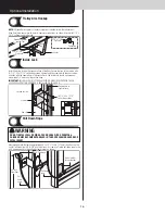
Attaching Track Roller Carrier’s
4
NOTE:
If you don’t have track roller carriers, then skip this step. Refer to Package Contents /
Breakdown of Parts, to determine if a track roller carrier was supplied with your door.
Starting on left hand side of the bottom section, attach the track roller carrier with the stamp
“STD” facing UP to the bottom corner bracket by aligning the four holes of the track roller
carrier with the four holes in the bottom corner bracket. Secure the track roller carrier to the
bottom corner bracket using 1/4” - 20 x 7/8” self drilling screws, as shown. Repeat for the
other track roller carrier and repeat the same process for the right hand side.
Insert a long stem track roller and spacer into the inner holes of the track roller carrier, as
shown. Repeat the same process for the right hand side.
NOTE:
The track roller carrier’s inner holes are used on doors with 2” track applications with
a short stem track roller; the outer holes are used on doors with 3” track applications with a
long stem track roller.
Bottom
section
Roller spacer
Long stem track roller
Bottom corner
bracket
1/4”-20 x 7/8”
Self drilling screws
Track roller
carrier’s
Inner
holes
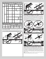
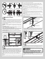
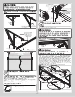
Attaching Top Fixtures To Top Section
5
NOTE:
Depending on your door, you may have Top Fixture Bases and Top Fixture Slides or
you may have Top Fixture Assemblies. Refer to Package Contents / Breakdown of Parts, to
determine which Top Fixtures you have.
IF YOU HAVE TOP FIXTURE ASSEMBLIES:
Starting on the left hand side, align the top
fixture base 3” down from the top section or below strut and even with the edge of the top
section. The slotted half of the top fixture base should be facing upwards. Fasten to section
through end cap using (4) 1/4” - 20 x 11/16” self drilling screws. Insert short stem track
roller into top fixture slide. Repeat for other side.
NOTE:
The top fixture slide will be tightened and adjusted later, in step, Adjusting Top Fixture.
NOTE:
Ensure the top fixture slide is able to slide along the top fixture base. If needed, loosen
the 1/4” - 20 flange hex nuts.
(4) 1/4”-20 x 11/16”
Self drilling screws
Top fixture
base
End cap
Top fixture slide
Top section
(2) 1/4”-20
Flange hex nuts
3”
Insert short
stem track roller
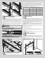
IF YOU HAVE 2 TOP FIXTURE BASES AND 2 TOP FIXTURE SLIDES:
Starting on the left
hand side of the top section, align the lip of the top fixture base onto the top corner of the top
section and even with the edge of the end cap. Fasten to section through end cap using (4)
1/4” - 20 x 11/16” self drilling screws. Loosely secure the top fixture slide to the top fixture
base using (1) 5/16” - 18 x 3/4” carriage bolt and (1) 5/16” - 18 hex nut. Insert short stem
track roller into top fixture slide. Repeat for other side.
NOTE:
The top fixture slide will be tightened and adjusted later, in step, Adjusting Top Fixture.
NOTE:
Ensure the top fixture slide is able to slide along the top fixture base. If needed, loosen
the 5/16” - 18 hex nut.
1/4”-20 x 11/16”
Self drilling screws
Top fixture
base
End cap
Insert short
stem track roller
Top section
Top fixture
base
5/16”-18 x 3/4”
Carriage bolt
5/16”-18 Hex nut
Top fixture
slide
Lip
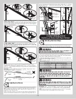
IF YOU HAVE 4 TOP FIXTURE BASES AND 4 TOP FIXTURE SLIDES:
Starting on the left
hand side of the top section, align the lip of the top fixture base onto the top corner of the
top section and even with the edge of the end cap. Fasten to section through end cap using
(4) 1/4” - 20 x 11/16” self drilling screws. Loosely secure the top fixture slide and the “L”
reinforcement bracket to the top fixture base using (1) 5/16” - 18 x 3/4” carriage bolt and (1)
5/16” - 18 hex nut. Fasten the “L” reinforcement bracket to section through end cap using
(1) 1/4” - 20 x 11/16” self drilling screw. Repeat the same process for the other top fixture.
Insert long stem track roller into top fixture slides. Repeat for other side.
NOTE:
The top fixture slides will be tightened and adjusted later, in step, Adjusting Top
Fixture.
NOTE:
Ensure the top fixture slides are able to slide along the top fixture bases. If needed,
loosen the 5/16” - 18 hex nuts.
1/4”-20 x 11/16”
Self drilling screws
Top fixture
base
End cap
Insert long stem
track roller
Top section
Top fixture
base
5/16”-18 x 3/4”
Carriage bolt
5/16”-18 Hex nut
Top fixture
slide
Lip
“L” Reinforcing
bracket
Attaching Hinges and Struts
6
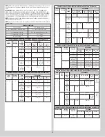
NOTE:
Refer to door section identification, located in the pre-installation section of this
manual to determine what size sections you need to use as your lock (second) section, inter-
mediate (third) section, intermediate (fourth) section and top section. Measure your sections
to make sure they are the correct height as indicated on the chart.
NOTE:
The graduated end hinges can be identified by the number stamped on the lower
hinge leaf. The #1 graduated end hinges serves as end hinges on the bottom section. The #1
graduated end hinges also serves as center hinges on all sections, except for the top section.
NOTE:
The #2 graduated end hinges serves as end hinges on the Lock section.
NOTE:
The #3 graduated end hinges serves as end hinges on the Intermediate I section.
NOTE:
The #4 graduated end hinges serves as end hinges on the Intermediate II section.
7


