


5/16”-18 x 3-3/4”
Eye bolt
Special
knot
3 Hole
clip
Rear
back
hang
Spring restraint
cable
Special
knot
5/16”-18 x 3-3/4”
Eye bolt
5/16”-18
Hex nut
Extension
spring
Horizontal track
5/16”-18
Hex nut
Horizontal track
5/16”-18
Hex nut
6”-8”
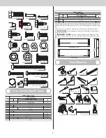
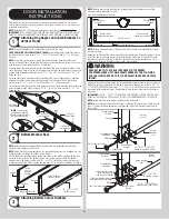
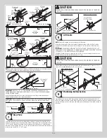
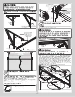
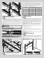
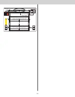
Attaching Spring Sheaves
19
Hook the sheave fork through the front loop of the extension spring and attach the sheave
fork to the rear cable lift sheave using (1) 3/8” - 16 x 1-1/4” hex head bolt and (1) 3/8” - 16
hex nut. Thread the counterbalance lift cable over the front cable lift sheave and around the
rear cable lift sheave and tie the special knot around the “horizontal angle” using a 3 hole
clip, as shown.
Insert one end of the large “S” hook into the “horizontal angle” with the 3 hole clip and the
other end into the second slot of the horizontal angle, as shown. Repeat for the other side.
IMPORTANT:
CLOSE “S” HOOKS AND EYE BOLTS WITH LOCKING PLIERS, TO PREVENT
SPRINGS FROM COMING LOOSE.
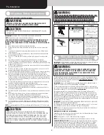
WARNING
FAILURE TO CLOSE “S” HOOKS AND EYE BOLTS CAN RESULT IN SEVER
OR FATAL INJURY IF SPRINGS COME LOOSE.
Rear
cable lift
sheave
Sheave fork
Horizontal track
Hook plate
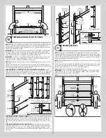
This illustration shows doors featuring (2) pairs of extension springs
Counterbalance
lift cable
Counterbalance
lift cable
Spring restraint
cable
NOTE:
Some larger doors feature 2 pairs of extension springs. A spring restraint cable must
be installed through each spring.
Horizontal
track
Rear back hang
Extension
spring
3/8”-16 x 1-1/4”
Hex head bolt
3/8” - 16
Hex nut
Sheave fork
Extension spring
Rear cable
lift sheave
Sheave fork
Extension spring
Rear cable
lift sheave
3 Hole clip
Special
knot
Counterbalance
lift cable
“S”
Hook
“S”
Hook
Spring
restraint
cable
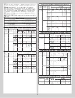
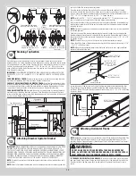
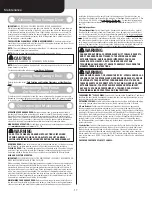
Counterbalance Lift Cable Adjustments
20
Adjust counterbalance lift cables to create about 1” to 2” (25 mm to 50 mm) of initial exten-
sion spring stretch, with the door in the fully opened position. Measure relaxed extension
spring length for your door height and verify with the chart below. Spring length must be the
same for both extension springs to allow even door balance. Carefully remove the locking
pliers from the horizontal track and lower the door into the closed position. Once the door is
closed, measure the extension spring length in tension for both sides. Using the chart, verify
the spring length in tension is correct with your door height.
NOTE:
It may be necessary to adjust spring length for proper door balance.
Door Height
Spring Length Relaxed (Door
Open)
Spring Length Extended
(Door Closed)
6’ 0”
25” (635 mm)
61” (1549 mm)
6’ 3”
25” (635 mm)
62-1/2” (1588 mm)
6’ 6”
25” (635 mm)
64” (1626 mm)
7’ 0”
25” (635 mm)
67” (1702 mm)
7’ 6”
27” (686 mm)
72” (1829 mm)
7’ 9”
27” (686 mm)
73-1/2” (1867 mm)
8’ 0”
27” (686 mm)
75” (1905 mm)
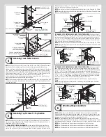
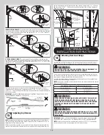
Balancing Door
21
Lift door and check its balance. If door rises off floor more than 2 ft. under spring tension
alone, reduce spring tension by adjusting extension spring length, moving the “S” hook back-
ward (towards the rear back hangs) to a different hole in the horizontal track. If the door is
hard to rise or drifts down on its own, adjust extension spring length by moving the “S” hook
forward (towards the header) to a different hole in the horizontal track. A poorly balanced
door can cause garage door operator problems.
IMPORTANT:
WHENEVER ADJUSTING EXTENSION SPRING LENGTH FOR DOOR BALANCE,
ALWAYS OPEN THE DOOR TO THE FULLY OPEN POSITION AND RETURN THE LOCKING
PLIERS, AS SHOWN IN F3 TO THE HORIZONTAL TRACKS BELOW THE BOTTOM TRACK
ROLLERS.
If the door still does not operate easily, raise the door into the open position, return the lock-
ing pliers, and recheck the following items:
1.) Is the door level?
2.) Are the flag angles level and plumb?
3.) Does the distance between the flag angles equal door width plus 3-3/8” to 3-1/2”?
4.) Do the counterbalance lift cables have equal tension? Adjust by re-tieing the special knot,
if necessary.
5.) Make sure door is not rubbing on jambs.
IMPORTANT:
IF DOOR STILL DOES NOT BALANCE PROPERLY, THEN CONTACT A TRAINED
DOOR SYSTEM TECHNICIAN.
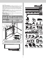
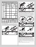
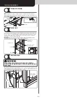
Attaching Weather Seal
22
Permanently attach the weatherstrips on both door jambs and header. The weatherstrips
were temporarily attached in Preparing the Opening, in the pre-installation section of this
manual.
NOTE:
When permanently attaching the weatherstrips to the jambs, avoid pushing the weath-
erstrips too tightly against the face of door.
Weather seal
s
Nail
Weather
seal
Jamb
Weather seal
installed
Jamb
Header
Jamb
Nail
NOTE:
Door not shown for clarity.
15


