
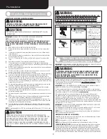


DOOR INSTALLATION
INSTRUCTIONS
Before installing your door, be certain that you have read and followed all of the instruc-
tions covered in the pre-installation section of this manual. Failure to do so may result in an
improperly installed door.
NOTE:
Reference TDS 160 for general garage door terminology at
www.dasma.com
.
IMPORTANT:
IF THE DOOR WILL BE EXPOSED TO A SIGNIFICANT AMOUNT OF ROAD SALT,
PAINT THE BARE GALVANIZED BOTTOM WEATHER STEEL RETAINER TO INHIBIT RUSTING.
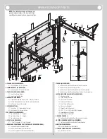
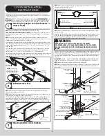
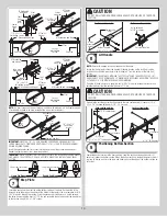
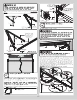
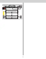
Attaching Flag Angles and Jamb Brackets To
Vertical Tracks
1
NOTE:
If you have Riveted Track or Angle Mount Track, skip this step.
FOR DOORS WITH FULLY ADJUSTABLE TRACK:
Hand tighten the left hand flag angle to
the left hand vertical track using (2) 1/4” - 20 x 9/16” track bolts and (2) 1/4” - 20 flange
hex nuts.
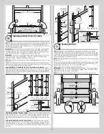
NOTE:
The bottom jamb bracket is always the shortest bracket, while the center jamb
bracket is the next tallest. If three jamb brackets per side are included with your door, you will
have received a top jamb bracket, which is the tallest.
To attach the bottom jamb bracket, locate lower hole of the hole/ slot pattern of the 1st hole
set on the vertical track. Align the slot in the jamb bracket with the lower hole of the hole/ slot
pattern. Hand tighten jamb bracket using (1) 1/4” - 20 x 9/16” track bolt and (1) 1/4” – 20
flange hex nut.
Place the center jamb bracket over the lower hole of the hole/ slot pattern that is centered
between the bottom jamb bracket and flag angle of the 2nd hole set. Hand tighten jamb
bracket using (1) 1/4” - 20 x 9/16” track bolt and (1) 1/4” - 20 flange hex nut.
If a top jamb bracket was included, hand tighten it to vertical track using the lower hole of the
hole/ slot pattern in the 3rd hole set and (1) 1/4” - 20 x 9/16” track bolt and (1) 1/4” - 20
flange hex nut.
Left hand
vertical track
NOTE:
Loosely fasten
components together.
Repeat the same process
for the right hand side.
Left hand
flag angle
Left hand
jamb bracket
Left hand
jamb bracket
3rd
Set
1st
Set
2nd
Set
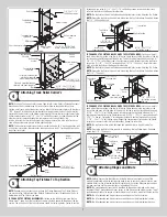
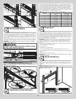
Bottom Weather Seal
2
NOTE:
Refer to door section identification, located in the pre-installation section of this
manual or refer to Breakdown Of Parts.
NOTE:
Verify that the bottom weather seal is aligned with bottom section. If needed, trim the
bottom weather seal even with bottom section length.
Position the bottom weather seal up against the bottom of the bottom section with the long
lip on the inside surface of the bottom section. From inside the door, attach the bottom
weather seal to the bottom section with 1/4” - 20 x 7/8” self drilling screws, placing one 6”
in from each end of the bottom section and one every 18” (maximum) in between, as shown.
Endcap
Bottom weather seal
1/4”-20 x 7/8” Self
drilling screws
Long lip
Inside
surface
of bottom
section
Inside surface of
bottom section
6”
18”
Endcap
18”
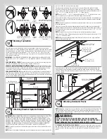
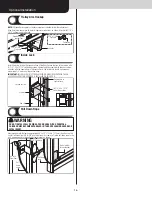
Attaching Bottom Corner Brackets
3
NOTE:
Refer to door section identification, located in the pre-installation section of this
manual or refer to Breakdown of Parts.
Uncoil the counterbalance lift cables.
Bottom weather seal
Cable loop
Bottom section
Cable loop
Bottom corner
bracket warning label
Bottom corner
bracket warning label
Counterbalance
lift cable
Counterbalance
lift cable
NOTE:
Refer to Package Contents / Breakdown of Parts, to determine which bottom corner
brackets you have.
Depending on which bottom corner brackets you have (reference illustrations below), slip the
loop at the ends of the counterbalance lift cable over the milford pin of the bottom corner
bracket or secure the cable loop to the clevis pin and bottom corner bracket using a flat
washer and a cotter pin. Repeat for other bottom corner bracket.
WARNING
ENSURE TIGHT FIT OF CABLE LOOP OVER PIN TO PREVENT
COUNTERBALANCE LIFT CABLE FROM COMING OFF THE PIN, WHICH
COULD ALLOW THE DOOR TO FALL AND RESULT IN SEVERE OR FATAL
INJURY.
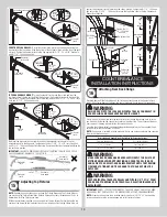
Starting on the left hand side, attach the left hand bottom corner bracket to the left corner of
the bottom section, making sure it is seated to the edges of the end cap, using (3) 1/4” - 20
x 11/16” RED HEAD self drilling screws, 1/4” - 20 x 11/16” self drilling screws. Insert a short
stem track roller with roller spacer (if applicable) into the bottom corner bracket. Repeat for
other side.
IMPORTANT:
THE 1/4” - 20 X 11/16” RED HEAD SELF DRILLING SCREWS MUST BE MUST
BE INSTALLED THROUGH THE HOLES OF THE BOTTOM CORNER BRACKETS, AS SHOWN.
NOTE:
Check to ensure cable loop fits tightly over the milford pins.
NOTE:
Verify bottom weather seal (bottom seal) is aligned with door section. If there is more
than 1/2” excess bottom weather seal on either side, trim bottom weather seal even with
door section.
Roller spacer
Counterbalance
cable loop
Short stem track roller
Milford pin
Bottom corner
bracket
End cap
Counterbalance
lift cable
Bottom
weather
seal
Bottom
section
(3) 1/4”-20 x 11/16” Self
drilling screws (RED HEAD )
End cap
Counterbalance
lift cable
Bottom weather
seal
Bottom
section
Short stem track roller
Bottom corner
bracket
1/4”-20 x 11/16”
Self drilling screws
Counterbalance
cable loop
Cotter pin (attached into
place from opposite
side of bottom bracket)
Clevis pin (inserted through
cotter pin and bent into place)
Washer
(3) 1/4”-20 x 11/16” Self
drilling screws (RED HEAD )
6


