background image

5 of 20

WX-501-0517 • 05.22

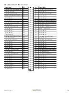
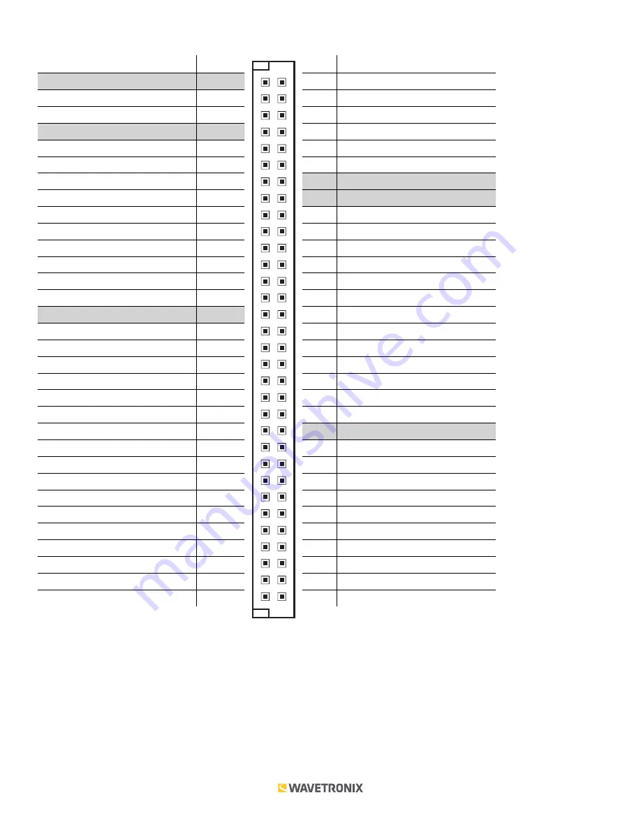
Click 110 pinout with Siemens outstation

Description

Pin

Channel 1 fault, normally open

B1

Channel 1 common

B2

Channel 1 fault common

B3

Master fault, normally open

B4

No connection

B5

No connection

B6

No connection

B7

Channel 2, normally closed

B8

No connection

B9

Channel 2, normally open

B10

No connection

B11

No connection

B12

No connection

B13

Chassis ground

B14

Channel 3 fault, normally open

B15

Channel 3 common

B16

Channel 3 fault common

B17

No connection

B18

No connection

B19

No connection

B20

No connection

B21

Channel 4, normally closed

B22

No connection

B23

Channel 4, normally open

B24

No connection

B25

No connection

B26

No connection

B27

No connection

B28

No connection

B29

+DC (12–24 VDC)

B30

No connection

B31

-DC (common)

B32

Pin

Description

A1

Channel 1, normally closed

A2

No connection

A3

Channel 1, normally open

A4

No connection

A5

No connection

A6

No connection

A7

Master fault, normally closed

A8

Channel 2 fault, normally open

A9

Channel 2 common

A10

Channel 2 fault common

A11

Master fault common

A12

No connection

A13

No connection

A14

No connection

A15

Channel 3, normally closed

A16

No connection

A17

Channel 3, normally open

A18

No connection

A19

No connection

A20

No connection

A21

No connection

A22

Channel 4 fault, normally open

A23

Channel 4 common

A24

Channel 4 fault common

A25

No connection

A26

No connection

A27

No connection

A28

No connection

A29

Reset

A30

No connection

A31

No connection

A32

No connection

A1

Summary of Contents for Click 110

Page 1: ...1 21 24 1 1 1 0 25 28 1 1 1 1 29 32 S3 Channel Enable 4 5 6 7 8 Channel 0 SW Con g 1 1 1 2 1 3 1 4 S1 Bus 2 Baud Rate 5 6 7 8 Value 0 SW Con g 1 0 0 0 9600 1 0 0 1 19200 1 0 1 0 38400 1 0 1 1 57600 1...

Page 2: ...s numbered 1 4 left to right Level 1 LEDs display which menu is active These Level 1 LEDs are dual purpose each indicating both menu selection as well as a normal operation state when not in Menu mode...

Page 3: ...hain together all the cards you intend to use in your installation using short RJ 11 jumper cables 4 Connect the first Click 110 card to the SmartSensor via a surge protector such as the Click 200 222...

Page 4: ...ction B25 No connection B26 No connection B27 No connection B28 No connection B29 DC 12 24 VDC B30 No connection B31 DC common B32 Pin Description A1 Channel 1 normally closed A2 No connection A3 Chan...

Page 5: ...tion B25 No connection B26 No connection B27 No connection B28 No connection B29 DC 12 24 VDC B30 No connection B31 DC common B32 Pin Description A1 Channel 1 normally closed A2 No connection A3 Chann...

Page 6: ...ument Configuration The Click 110 can be configured in three ways DIP switches the front panel menu and Click Supervisor These three different configuration methods can configure different sets of opt...

Page 7: ...tstation mode Fault latch Each parameter except fault latch and outstation mode has a way to pick between Hardware Software modes If Software mode is selected the parameter must be configured using th...

Page 8: ...If switch 1 5 is off down Software mode is selected and Click Supervisor and the front panel menu will be able to both display and change the current setting Channel enable The next parameter that ca...

Page 9: ...output channels only four input datagram channels received from the sensor can be output by each device If you need more than four channels consider using multiple devices As shown in the table below...

Page 10: ...configuration modes Fault latch The last option that can be configured on the DIP switches is fault latching This is configured on the third DIP switch labeled S3 using switch 8 S3 8 Note This paramet...

Page 11: ...ower bank also function as activity status indicators These functions outlined in the Physical Features section of this document are only executed when the device is not in Menu mode In this case the...

Page 12: ...ase how to autobaud bus 2 Mode switch action Display State None Normal operation Press and hold Channel map menu option displayed Continue holding Autobaud menu option displayed Release Autobaud menu...

Page 13: ...ged using the DIP switches or Click Supervisor As mentioned earlier the Click 110 device receives serial datagrams from a SmartSensor These datagrams can contain many channels of detection data Becaus...

Page 14: ...buses you will select which bus to autobaud on the Level 2 LEDs An autobaud will stop data reporting on the selected port and attempt to communicate with the SmartSensor at all supported baud rates Le...

Page 15: ...default 19200 bps 38400 bps 57600 bps LED off Cancel and exit menu LED on See the earlier Navigating through the Menu and the Menu Operation Example sections for how to configure this parameter Becau...

Page 16: ...on Example sections for how to configure this parameter Because this parameter can also be set by the DIP switches you may need to ensure that the DIP switches are set to Software configuration mode i...

Page 17: ...eptions are fault latch and outstation mode which are not reset by this option Level 1 LEDs Reset to default settings Level 2 LEDs Reset to default settings LED off Cancel and exit menu LED on See the...

Page 18: ...ral tab lets you change general information about your device The tab has the following parameters see the figure and table below Note This parameter can only be configured using Click Supervisor Sett...

Page 19: ...Bus 1 Lets you change the baud rate in bps of bus 1 Baud Rate for Bus 2 Lets you change the baud rate in bps of bus 2 Input Mapping Lets you assign input datagram channels received from the sensor to...

Page 20: ...problems are detected a green circle will appear Once you have finished use the menu bar at the top of the screen to save your settings return to the Select Driver screen and more The Save menu allows...

Reviews: