1726 North Ballard Road, Suite 1 - Appleton, WI 54911 - 920.991.9082
Technical Support 855.804.5774 - [email protected]
PTM30045-F
22 FEB 2018
W
E
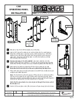
1 Remove screws from COP and place in a safe place.
2. Locate COP hole in the elevator car wall and measure the wall thickness.
Place the COP brackets in position on the COP electrical box. Off set the
brackets from the front edge of the COP electrical box by the distance
measured. Fasten the (4) COP brackets to COP electrical box with the
following provided hardware.
For elevator series 114, 021 and 022
route slack cable fl ex into the
bottom of the COP box and fasten. Connect (2) slack cable plugs together
inside the COP box. The 2x4 enclosure should hang below the elevator car.
4. Slide COP cover plate through the COP hole in the elevator car wall.
Be careful not to scratch any surfaces or pull out any factory wires.
5. Place COP enclosure with secured brackets into COP hole and fasten to wall
using the provided hardware.
Note:
The installer may have to square off the corners or weld spots of the
COP hole in the elevator car wall to fi t the COP enclosure properly. While
doing this verify the interior of the elevator car wall is not being damaged or
accidentally making the COP hole larger than it should be.
Verify that the provided screws do not pierce through the interior wall of
the elevator car.
6 Fasten COP cover plate onto COP enclosure with previously removed screws.
NOTE:
Some wires not shown
for clarity. Install prior
to car wall installation.
Slack cable plugs
contained in the COP are
only used for Series 114,
021 & 022 units.
CAR
OPERATING PANEL
INSTALLATION
SERIES :
008, 114 , 116, 118, 021, 022, 210
1, 6
2
CRUSH
HAZARD
CUTTING
HAZARD
CRUSH
HAZARD
CRUSH
HAZARD
CRUSH
HAZARD
CRUSH
HAZARD
ELECTRIC
HAZARD
FALLING
HAZARD
CRUSH
HAZARD
PINCH
HAZARD
ANTI-
STATIC
ALERT
1.
4.
3
2.
4
3.
6.
COP
Cover
Plate
COP Panel
Elevator
Car Wall
Brackets x4
Screws x2
COP
Electrical
Box
Page 29


