


TOWINg A ND TR A NSPORTINg
117
W L 30
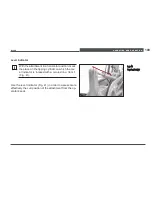
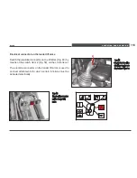
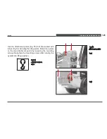
To tow the loader, it is necessary that you disconnect the
drive. In this case the travel transmission is switched on to
free wheeling. For this purpose the variable displacement
pump has incorporated high pressure relief valves with
bypass function.
1.
Tilt the operator cab/platform upward from the left side
for access to the high pressure relief valves (refer to
Section 10.7.1, pages 158-161).
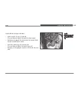
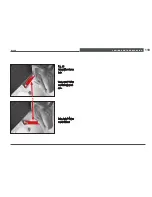
2. Loosen hex nut Item 2 (Fig. 52).
3. Screw in the stud Item 1 (Fig. 52) until it is level with the hex nut.
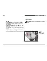
Note:
Turn the studs Item. 1 (Fig. 52) no further than
described, otherwise parts of the valve become dam-
aged.
4.
Return the operator cab/platform to operating position
and follow instructions provided in Section 10.7.1, pages
158-161 to securely fasten the operator cab/platform in
the normal operating position.
5. The Wheel Loader can be towed.
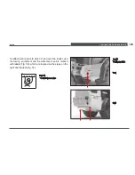
After towing:
1.
Tilt the operator cab/platform upward from the left side
for access to the high pressure relief valves (refer to
Section 10.7.1, pages 158-161).
2. Screw back stud Item 1 (Fig. 52) to stopper.
3. Tighten hex nut Item 2 (Fig 52) to a torque of 22 Nm
(16 ft.lbs.).
Summary of Contents for WL 30
Page 1: ...www wackerneuson com Operator s Manual Wheel Loader WL 30...
Page 2: ...December 10 Edition...
Page 17: ...BASIC INFORMATION 15 WL30...
Page 48: ...TECHNICAL DATA 46 3 4 Dimensions Fig 11 Dimensions...
Page 61: ...Description of the indicator warning and control elements 59 WL30...
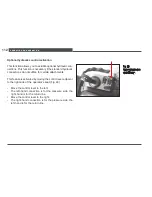
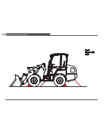
Page 126: ...Towing and transporting 124 Fig 58 Tying down the loader...
Page 161: ...SERVICING AND INSPECTION 159 WL30 2 1 Fig 63 Cab tilt lever...
Page 235: ...Appendix 233 WL30 For personal notes...
Page 245: ...List of figures 243 WL30...


