BA E16 en* 1.0 * E16_10_510.fm
5-53
Operation 5
Connecting and disconnecting hydraulic couplings
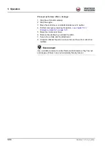
1. Stop and park the vehicle
– see chapter “ Preparing lubrication” on
2. Position the boom straight ahead at the center of the vehicle.
3. Lower the stabilizer blade to the ground.
4. Turn the starting key to position
1
.
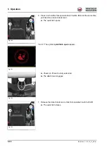
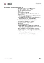
5. Move the control lever or the pedal of the hydraulic circuit in all
directions repeatedly.
6. Remove the starting key and carry it with you.
➥
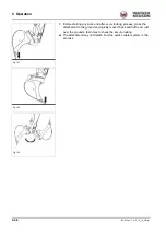
The grab hose couplings can now be coupled and uncoupled from the
couplings.
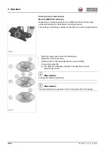
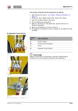
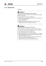
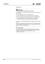
Hydraulic connections
Information
Follow the instructions in the operator’s manual of the attachment
manufacturer for connecting the hydraulics to the attachment.
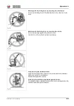
Fig. 217
A
B
C
Connec-
tion
Stick (left/right)
A
AUX V (option)
B
AUX II or AUX III (option)
C
AUX I
D
Hydraulic thumb (option)
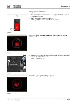
Fig. 218
C
A
B
Fig. 219
D
Summary of Contents for ET35
Page 14: ...1 8 BA E16 en 1 0 E16_10_100 fm 1 Foreword Notes...
Page 46: ...3 8 BA E16 en 1 0 E16_10_300 fm 3 Introduction Warning labels Fig 9 symbolic representation...
Page 64: ...3 26 BA E16 en 1 0 E16_10_300 fm 3 Introduction Notes...
Page 194: ...6 8 BA E16 en 1 0 E16_10_600 fm 6 Transportation Notes...
Page 252: ...8 8 BA E16 en 1 0 E16_10_800 fm 8 Malfunctions Notes...
Page 292: ...9 40 BA E16 en 1 0 E16_10_900 fm 9 Technical data 9 15 Dimensions ET35 symbolic representation...
Page 294: ...9 42 BA E16 en 1 0 E16_10_900 fm 9 Technical data EZ36 symbolic representation...
Page 296: ...9 44 BA E16 en 1 0 E16_10_900 fm 9 Technical data Notes...
Page 300: ...S 4 BA E16 en 1 0 E16_10_3SIX fm...

