BA E16 en* 1.0 * E16_10_510.fm
5-47
Operation 5
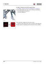
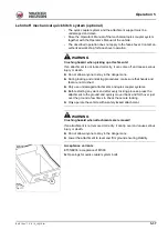
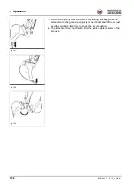
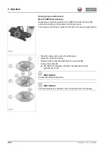
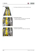
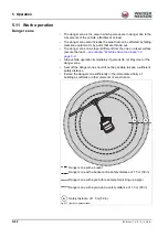
Manual HSWS bolt lock
Depending on national provisions, the HSWS must also be manually
locked according to the hydraulic locking process.
The locking or unlocking is located to the left on the quick coupler system.
• Stop the engine and remove the starting key.
• Raise the control lever base.
• Rotate bolt
A
so that the pin
B
fits in the recess
C
(2)
.
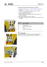
• Press in bolt
A
and turn until it is held in its position by spring
(3)
.
➥
The HSWS is also manually locked.
Information
Comply with national provisions.
Information
The bolt positions may deviate in their final position from the figures.
Fig. 200
Fig. 201 (symbolic representation)
1
2
3
A
A
A
C
B
Summary of Contents for ET35
Page 14: ...1 8 BA E16 en 1 0 E16_10_100 fm 1 Foreword Notes...
Page 46: ...3 8 BA E16 en 1 0 E16_10_300 fm 3 Introduction Warning labels Fig 9 symbolic representation...
Page 64: ...3 26 BA E16 en 1 0 E16_10_300 fm 3 Introduction Notes...
Page 194: ...6 8 BA E16 en 1 0 E16_10_600 fm 6 Transportation Notes...
Page 252: ...8 8 BA E16 en 1 0 E16_10_800 fm 8 Malfunctions Notes...
Page 292: ...9 40 BA E16 en 1 0 E16_10_900 fm 9 Technical data 9 15 Dimensions ET35 symbolic representation...
Page 294: ...9 42 BA E16 en 1 0 E16_10_900 fm 9 Technical data EZ36 symbolic representation...
Page 296: ...9 44 BA E16 en 1 0 E16_10_900 fm 9 Technical data Notes...
Page 300: ...S 4 BA E16 en 1 0 E16_10_3SIX fm...

