BA E16 en* 1.0 * E16_10_510.fm
5-33
Operation 5
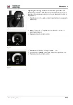
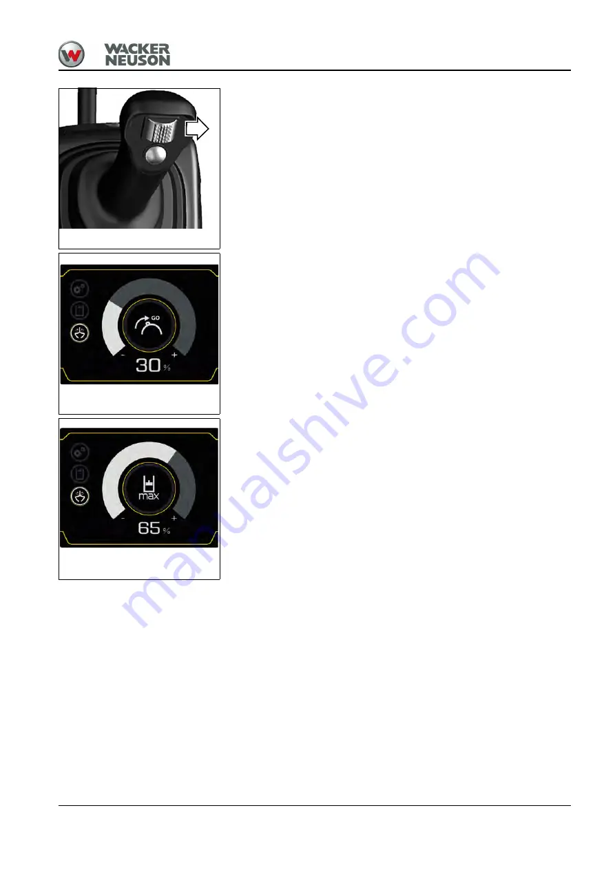
Adjusting the starting point and maximum required flow rate
The starting point of the control lever switch and the maximum required
flow rate can be configured according to the attachment and the work to
be performed.
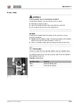
1. Press the switch to the position at which the attachment is supposed to
start moving.
2. Hold the switch and turn adjustment button
A
at the same time to
select the starting point.
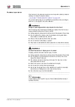
3. Press adjustment button
A
to confirm.
4. Press the switch as far as it will go and hold it there.
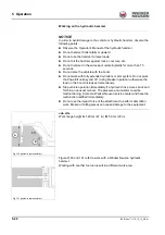
5. Turn adjustment button
A
to select the maximum required flow rate.
6. Press adjustment button
A
to confirm.
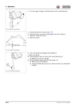
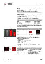
Fig. 170
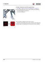
Fig. 171
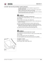
Fig. 172
Summary of Contents for ET35
Page 14: ...1 8 BA E16 en 1 0 E16_10_100 fm 1 Foreword Notes...
Page 46: ...3 8 BA E16 en 1 0 E16_10_300 fm 3 Introduction Warning labels Fig 9 symbolic representation...
Page 64: ...3 26 BA E16 en 1 0 E16_10_300 fm 3 Introduction Notes...
Page 194: ...6 8 BA E16 en 1 0 E16_10_600 fm 6 Transportation Notes...
Page 252: ...8 8 BA E16 en 1 0 E16_10_800 fm 8 Malfunctions Notes...
Page 292: ...9 40 BA E16 en 1 0 E16_10_900 fm 9 Technical data 9 15 Dimensions ET35 symbolic representation...
Page 294: ...9 42 BA E16 en 1 0 E16_10_900 fm 9 Technical data EZ36 symbolic representation...
Page 296: ...9 44 BA E16 en 1 0 E16_10_900 fm 9 Technical data Notes...
Page 300: ...S 4 BA E16 en 1 0 E16_10_3SIX fm...

