4-18
BA E16 en* 1.0 * E16_10_400.fm
4 Putting into operation
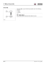
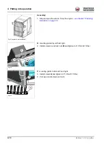
Assembly
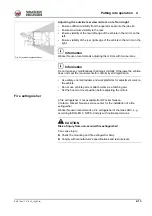
1. Stop and park the vehicle. Stop the engine
K
: mounting points top left and right.
2. Install screws
L
and lock nuts
M
and tighten to 110 Nm (81 ft.lbs.).
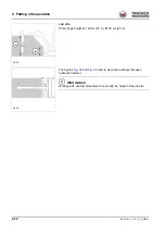
P
: mounting points bottom left and right.
3. Install screws
Q
and tighten to 110 Nm (81 ft.lbs.).
4. Put caps on all screws and nuts.
Fig. 95 (symbolic representation)
Fig. 96
K
L
M
Fig. 97
P
Q
Summary of Contents for ET35
Page 14: ...1 8 BA E16 en 1 0 E16_10_100 fm 1 Foreword Notes...
Page 46: ...3 8 BA E16 en 1 0 E16_10_300 fm 3 Introduction Warning labels Fig 9 symbolic representation...
Page 64: ...3 26 BA E16 en 1 0 E16_10_300 fm 3 Introduction Notes...
Page 194: ...6 8 BA E16 en 1 0 E16_10_600 fm 6 Transportation Notes...
Page 252: ...8 8 BA E16 en 1 0 E16_10_800 fm 8 Malfunctions Notes...
Page 292: ...9 40 BA E16 en 1 0 E16_10_900 fm 9 Technical data 9 15 Dimensions ET35 symbolic representation...
Page 294: ...9 42 BA E16 en 1 0 E16_10_900 fm 9 Technical data EZ36 symbolic representation...
Page 296: ...9 44 BA E16 en 1 0 E16_10_900 fm 9 Technical data Notes...
Page 300: ...S 4 BA E16 en 1 0 E16_10_3SIX fm...

