24
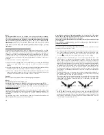
mV
= millivolt (exp.-3)
V
= volt (unit of electric potential)
A
= ampere (unit of electric current)
mA
= milliampere (exp.-3)
µA
= microampere (exp.-6)
Hz
= Hertz
kHz
= kilohertz (exp.3)
MHz
= megahertz (exp.6)
k
Ω
= kiloohm (exp.3)
M
Ω
= megaohm (exp.6)
nF
= nanofarad (nano = exp.-9)
µF
= microfarad (micro = exp.-6)
B Button layout and functional description with key input
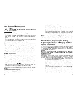
B 1 RANGE
RANGE bedeutet, wörtlich übersetzt, Bereich. It refers to the measuring range. As
soon as the „AUTO“ symbol (black background) becomes visible in the display, you
do not need to select the correct, adjusted measuring range. The intelligence of the
measuring instrument switches for you. But the measuring range can also be
changed manually. To do this, proceed as follows:
- Press the „RANGE“ button; the „AUTO“ symbol will disappear.
- Now, each further activation of the „RANGE“ button changes the measuring
range. This change is indicated by the movement of the decimal point and pos-
sibly by the change of the measuring unit.
If you want to leave the manual setting, press the „RANGE“ button and hold it for
longer than 1s (keep it pressed).
B 2 „Hz %“
If the rotary switch is set to „Hz“, this button will be relevant. You do not need this
button for the real measurement of frequency. If you like to indicate the pulse-pause
ratio instead of the normal frequency measurement (for TTL levels), you have to
press this button once.
Instead of the frequency indication in HZ, kHz or MHz, the pulse-pause ratio, also
called DUTY CYCLE, is indicated in % now. By pressing the button anew, you return
to the normal frequency measurement.
B 3 REL
The reference value measurement indicated by the triangle symbol allows measure-
ments which refer to a previously indicated / measured value. Now, the difference
value is indicated (current measuring value minus reference value).
This function is particularly useful for measuring resistance values. The main indica-
tion can be set to „0000“. Thus, you can measure values in the low-resistance range
without being forced to always reduce the line resistance of the instrument leads
from the value measured.
The reference value measurement is not possible for frequency and pulse-pause
33
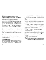
Fault
Possible cause
No measurement possible Are the measuring lines correctly connected to the
measuring sockets?
Do the fuses work properly?
No display appears
Is the battery flat?
if the device is turned on
Frequency measurement
Is the measuring voltage (amplitude) sufficiently high
not possible
(> 300mVeff or 600mVeff)?
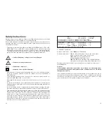
Technical Data and Measuring Tolerances
A Technical data
Display . . . . . . . . . . . . . . . . : 3
3
/
4
digit liquid crystal display (LCD), display size of
4000 counts
Speed of measurement . . . : 3 measurements per sec.
Input resistance . . . . . . . . . : > 10 MOhm
Over-voltage category . . . . : CAT III 1000V, CAT IV 600V
Battery replacement symbol: from lower than 7.5VDC ±0,5V
Voltage supply . . . . . . . . . . : 9V compound battery, type: NEDA 1604 6F22 or 006P
or 6LR61
Operating temperature . . . : 0°C to +40°C
Storage temperature . . . . . : -10°C to +50°C (batteries removed)
Rel. air humidity . . . . . . . . . : < 75%, non-condensing from 0°C to +30°C and
< 50%, non-condensing from 31°C to 40°C
Operating height . . . . . . . . : up to max. 2,000m above MSL
Temperature for guaranteed
accuracy . . . . . . . . . . . . . . : +23°C ±5K (=Kelvin)
Weight . . . . . . . . . . . . . . . . : ca. 300g (with battery, without measuring lines)
Dimensions (L x W x H) . . . : 177 x 85 x 40mm
B Measuring tolerances
Indication of accuracy in ±(% of the measurement value read + number of positions =
digits =dgt(s)).
Accuracy valid for 1 year at a temperature of +23°C ±5K, and at a relative humidity of
less than 75%, non-condensing. The warm-up time is 1 minute
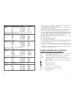
Operating mode
Measurement range Accuracy
Resolution
Direct
400mV
±(1.0% + 5 dgts)
0.1mV
voltage
4V
±(0.9% + 5 dgts)
1mV
40V
±(0.9% + 5 dgts)
10mV
400V
±(0.9% + 5 dgts)
100mV
1000V
±(1.4% + 5 dgts)
1V
Overload protection: 1000VDC lower than 10s


