


User Manual rev. 1.1. Aug. 2015
318
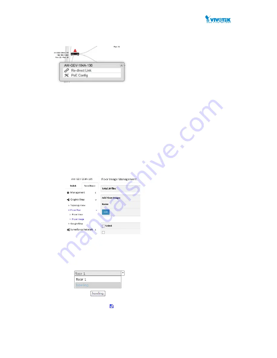
If you click on a surveillance switch, a PoE Config function is available that allows you to
control the PoE output on all switch ports, and to enable or disable the Auto Checking
function. The Auto Checking function intermittently examines the status of powered
devices, and report disconnection issue when the powered device cannot be reached.
8-2
Floor View
In this page, the administrator can place a device per time onto the custom image, which you
have already uploaded, by dragging-and-dropping markers in the device list.
You can upload up to 20 map files, with the limitation of 256KB in file size each.
Web interface
To configure the surveillance Floor View in the web interface:
1. Click Surveillance > Graphic View > Floor Plan > and Floor View.
2. Select a floor map you uploaded. You can prepare and upload one or multiple floor maps
in the Surveillance > Floor Plan > Floor Image window.
3. You then select a device on the Device List by a single click. A similar bubble icon will
appear on screen. Click and drag the icon to a preferred location on the map.
4. Repeat the above process until you finish the map setup, and click the
Apply
button.
5. With multiple maps in your deployment, e.g., different floor or building, select a different
floor view from the pull-down menu on top and continue with the configuration.
6.
Click the Save button
to save your configuration.
Summary of Contents for AW-GEV-104A Series
Page 66: ...User Manual rev 1 1 Aug 2015 66...
Page 137: ...User Manual rev 1 1 Aug 2015 137 values...
Page 183: ...User Manual rev 1 1 Aug 2015 183 values...
Page 195: ...User Manual rev 1 1 Aug 2015 195 Clear Clears the counters for all ports...
Page 241: ...User Manual rev 1 1 Aug 2015 241 Refresh Click to refresh the page...


