


Manual BG41/BG42/BG43
Interface modules
Rev. 99/49
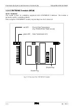
3-35
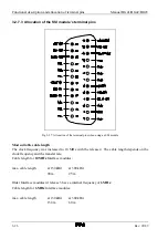
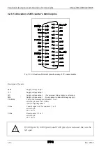
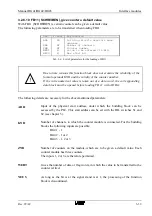
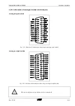
3.2.8.4 Allocation of 5V counter’s terminal pins
Fig. 3-33: Allocation of terminal pins when using a 5V counter module
Description of Signals:
Earth
:
Supply voltage output
+5V
:
Supply voltage output
CYa/BWa
:
Carry or borrow output of counters 1, 2 or 3
active: high - max. 5V, 100mA
inactive: high-impedance
UAxa-
:
Counter input 1 or 2 for counter 1, 2 or 3
active: low - TTL or RS 422 level
UAxa
:
Counter input 1 or 2 for counter 1, 2 or 3
active: high - only connect by differential drives
(RS 422), otherwise leave open
UA0a
:
Reset counters 1, 2 or 3
active: high - TTL or RS 422 level
UA0a-
:
Reset counters 1, 2 or 3
active: low - only connect by differential drives
(RS 422), otherwise leave open
If UA01(pin 10), UA02 (pin 6) and UA03 (pin 2) are not used, they must be
earthed!
Summary of Contents for SSM-BG41
Page 2: ...Lerrzeichen...
Page 8: ...Contents Manual BG41 BG42 BG43 iv Rev 99 49...
Page 10: ......
Page 16: ......
Page 26: ...Firmware s memory distribution Manual BG41 BG42 BG43 2 10 Rev 99 49...
Page 28: ......
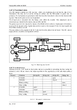
Page 53: ...Manual BG41 BG42 BG43 Interface modules Rev 99 49 3 25 3 2 7 2 Data flow Fig 3 26 Data flow...
Page 114: ...Functional description and allocation of terminal pins Manual BG41 BG42 BG43 3 86 Rev 99 49...
Page 116: ......
Page 215: ...Manual BG41 BG42 BG43 Software Rev 99 49 4 99 Month 06h Year 95h Weekday Tuesday 02h...
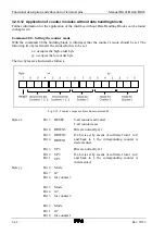
Page 222: ...Application of interfaces without data handling blocks Manual BG41 BG42 BG43 4 106 Rev 99 49...
Page 224: ......
Page 258: ...Structure guidelines Manual BG41 BG42 BG43 5 34 Rev 99 49...
Page 260: ......
Page 274: ...Overview cycle load Manual BG41 BG42 BG43 6 14 Rev 99 49...
Page 275: ...Appendix A List of figures A 1 B Index of tables B 1 C Index C 1...
Page 276: ......
Page 280: ...List of figures Manual BG41 BG42 BG43 A 4 Rev 99 49...


