


Presetting
Manual BG41/BG42/BG43
5-12
Rev. 99/49
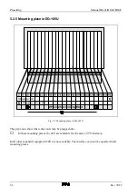
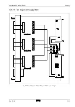
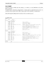
5.2.9 Voltage supply of the module
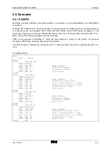
Internal voltage supply via the
back plane bus
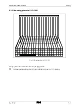
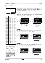
If the PLC on the bus provides 24V, the supply of the current
sources can take place via the bus. By means of the connector
field J6 on the base circuit board, one can choose if the 24V
should be taken from the top or the bottom base plug. If the top
base plug (X1) carries 24V, the jumpers are to be plugged as
follows (applies for PLC–115U):
Voltage supply via X1 for PLC-
115U
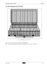
If the 24V are only available in the bottom base plug (X2) the
plug
connectors
are
to
be
plugged
as
follows
(applies for PLC-135U, PLC-150U, PLC-155U):
Voltage supply via X2 for PLC-
135U, PLC-150U, PLC-155U
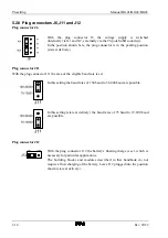
The plug connector J1 and J2 on the 20mA module
(or on the combination module) are to be brought into the
position for internal voltage supply "INT".
Summary of Contents for SSM-BG41
Page 2: ...Lerrzeichen...
Page 8: ...Contents Manual BG41 BG42 BG43 iv Rev 99 49...
Page 10: ......
Page 16: ......
Page 26: ...Firmware s memory distribution Manual BG41 BG42 BG43 2 10 Rev 99 49...
Page 28: ......
Page 53: ...Manual BG41 BG42 BG43 Interface modules Rev 99 49 3 25 3 2 7 2 Data flow Fig 3 26 Data flow...
Page 114: ...Functional description and allocation of terminal pins Manual BG41 BG42 BG43 3 86 Rev 99 49...
Page 116: ......
Page 215: ...Manual BG41 BG42 BG43 Software Rev 99 49 4 99 Month 06h Year 95h Weekday Tuesday 02h...
Page 222: ...Application of interfaces without data handling blocks Manual BG41 BG42 BG43 4 106 Rev 99 49...
Page 224: ......
Page 258: ...Structure guidelines Manual BG41 BG42 BG43 5 34 Rev 99 49...
Page 260: ......
Page 274: ...Overview cycle load Manual BG41 BG42 BG43 6 14 Rev 99 49...
Page 275: ...Appendix A List of figures A 1 B Index of tables B 1 C Index C 1...
Page 276: ......
Page 280: ...List of figures Manual BG41 BG42 BG43 A 4 Rev 99 49...


