


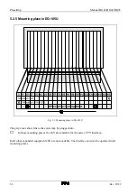


Presetting
Manual BG41/BG42/BG43
5-8
Rev. 99/49
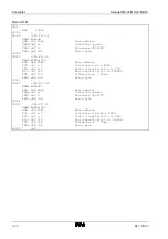
5.2.7 Setting the address with DIL switches S1 and S2
The start address, under which the interface building block can be operated by the automation
equipment, is set with the DIL switches S1 and S2. The addressing of the interface building block is
not dependant upon the mounting place! The address, under which it is controlled, is only dependant
upon the setting of the DIL switches and not from the mounting place in the SPS, i.e. it can occupy
any mounting place.
It is possible to set the interface building block in two modes.
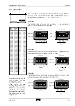
Absolute address
With the absolute addressing it is possible to use the entire address space of
the automation equipment as you like. For the interface building block
BG41, it must be divisible by 4 (without a remainder) and for the interface
building blocks BG42 and BG43 divisible by 8 (without a remainder). It is
required, that the selected address area is not already occupied by RAM or
other building blocks.
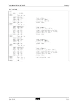
The interface building block BG42 occupies eight addresses and uses six
addresses, whereas the interface building block BG43 occupies and uses
eight addresses.
Peripheral address
With peripheral addressing the building block can only be addressed in a
particular area. In order to do this, bring the switch EG situated on the DIL
switch S1 into the ON position. The interface building block can therefore
be addressed in the peripheral area. In the peripheral area addresses can only
be used which do not run over the process image, i.e. the peripheral bytes
PYO and PY127 can not be used.
The interface building block can also be used in an expanded piece of
equipment. In this case one should observe, that the building block can still
only be addressed in the peripheral area.
If an IM building block is not used in the PLC 115U, the interface building
block may be used and by simulating the final plug a mounting place can be
saved. Both switches IM and EG on the DIL switch S1 must therefore be
switched to ON.
If the building block is not used on the IM mounting place, the switch IM on
the DIL switch S1 must be set to OFF!
Summary of Contents for SSM-BG41
Page 2: ...Lerrzeichen...
Page 8: ...Contents Manual BG41 BG42 BG43 iv Rev 99 49...
Page 10: ......
Page 16: ......
Page 26: ...Firmware s memory distribution Manual BG41 BG42 BG43 2 10 Rev 99 49...
Page 28: ......
Page 53: ...Manual BG41 BG42 BG43 Interface modules Rev 99 49 3 25 3 2 7 2 Data flow Fig 3 26 Data flow...
Page 114: ...Functional description and allocation of terminal pins Manual BG41 BG42 BG43 3 86 Rev 99 49...
Page 116: ......
Page 215: ...Manual BG41 BG42 BG43 Software Rev 99 49 4 99 Month 06h Year 95h Weekday Tuesday 02h...
Page 222: ...Application of interfaces without data handling blocks Manual BG41 BG42 BG43 4 106 Rev 99 49...
Page 224: ......
Page 258: ...Structure guidelines Manual BG41 BG42 BG43 5 34 Rev 99 49...
Page 260: ......
Page 274: ...Overview cycle load Manual BG41 BG42 BG43 6 14 Rev 99 49...
Page 275: ...Appendix A List of figures A 1 B Index of tables B 1 C Index C 1...
Page 276: ......
Page 280: ...List of figures Manual BG41 BG42 BG43 A 4 Rev 99 49...


