


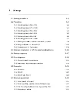


Manual BG41/BG42/BG43
Startup
Rev. 99/49
5-9
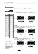
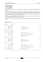
5.2.7.1 Examples
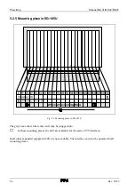
Three examples on addressing are shown in the following. With the
exclusion of the switches EG and IM (DIL switch S1) the addresses
are depicted in reverse (log. 1 == OFF, log. 0 == ON).
Example 1
The building block is be used in a central device and is controlled
under the start address PY128 (=F080h).
This classification table is
only
relevant
for
the
building block BG41.
With
regards
to
the
building blocks BG42 and
BG43 the position of the
switch A
2
is not evaluated
and therefore the addres-
ses ending in 4 or C are
not permitted.
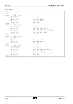
Example 2
The building block is used in an expanded piece of equipment and is
controlled under the start address PY224 (=F0E0).
Example 3
The building block is used on the IM position (PLC115-U only) and is
controlled under the start address PY200 (=F0C8h).
Summary of Contents for SSM-BG41
Page 2: ...Lerrzeichen...
Page 8: ...Contents Manual BG41 BG42 BG43 iv Rev 99 49...
Page 10: ......
Page 16: ......
Page 26: ...Firmware s memory distribution Manual BG41 BG42 BG43 2 10 Rev 99 49...
Page 28: ......
Page 53: ...Manual BG41 BG42 BG43 Interface modules Rev 99 49 3 25 3 2 7 2 Data flow Fig 3 26 Data flow...
Page 114: ...Functional description and allocation of terminal pins Manual BG41 BG42 BG43 3 86 Rev 99 49...
Page 116: ......
Page 215: ...Manual BG41 BG42 BG43 Software Rev 99 49 4 99 Month 06h Year 95h Weekday Tuesday 02h...
Page 222: ...Application of interfaces without data handling blocks Manual BG41 BG42 BG43 4 106 Rev 99 49...
Page 224: ......
Page 258: ...Structure guidelines Manual BG41 BG42 BG43 5 34 Rev 99 49...
Page 260: ......
Page 274: ...Overview cycle load Manual BG41 BG42 BG43 6 14 Rev 99 49...
Page 275: ...Appendix A List of figures A 1 B Index of tables B 1 C Index C 1...
Page 276: ......
Page 280: ...List of figures Manual BG41 BG42 BG43 A 4 Rev 99 49...


