Operation
NetCam1S, NetCam6, NetCamPlus Manual, © VCS GmbH
40
5
Operation
NetCam has no switches or other control elements. Once the system is installed, as
has been described in the preceding chapter, the unit is operational. Especially send-
ing units are mostly installed at distant locations, which are either called from the re-
ceiver side or may initiate a call in an alarm situation. Alternatively the NetCam
systems can be controlled via one of the RS232 interfaces using a keypad or a PC
with a suitable control program.
5.1
Front Panel Display
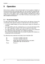
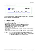
Four light-emitting diodes (LED) on the front side of the unit indicate to the user the
current status of the respective NetCam1 or NetCam6 unit (not for NetCamPlus):
•
A correctly installed adapter and the according power supply are indicated by a
red diode.
•
An existing ISDN connection is displayed by one or two green illuminated LED’s
‘B1’ or ‘B2’ depending on whether one or two B-channels are being used.
•
The yellow light ‘Detect’ signals motion detected in the video scene, whereupon
pre-configured emergency numbers can be dialed automatically.
When the Siemens M1 GSM-modem is connected the yellow LED indicates suc-
cessful login into the GSM network.
The following chart summarizes the meaning of each individual LED:
B1
Connection via ISDN channel B1
B2
Connection via ISDN channel B2
Detect
Motion detected (if motion detection is activated)
GSM network login (for Siemens M1)
Power
Power on
Summary of Contents for NetCam1
Page 1: ...NetCam1 NetCam6 NetCamPlus Manual VCS Video Communication Systems GmbH...
Page 6: ...NetCam1S NetCam6 NetCamPlus Manual VCS GmbH 6...
Page 42: ...NetCam1S NetCam6 NetCamPlus Handbuch VCS GmbH 42...
Page 80: ...Configuration Using NCTerm NetCam1S NetCam6 NetCamPlus Manual VCS GmbH 80...
Page 90: ...Appendix NetCam1S NetCam6 NetCamPlus Manual VCS GmbH 90...


