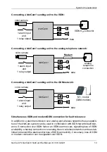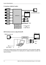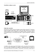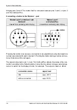
Hardware Installation
NetCam1S, NetCam6, NetCamPlus Manual, © VCS GmbH
22
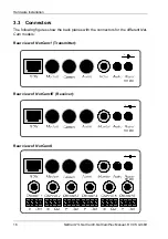
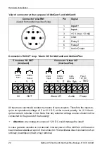
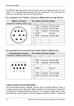
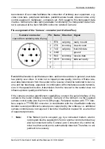
’Alarm’ connector at the rear panel of NetCam1 and NetCam6:
Connectors ’IN OUT’ resp. ’Alarm I/O’ for NetCam6 and NetCamPlus:
All inputs are electrically isolated by means of opto-couplers. Therefore the inputs re-
quire an operational voltage of 5 to 12 V DC, at the correct polarity. At 12 V the re-
quired current is below 4 mA. Note that any external voltage source should not be
connected to the ground of the housing!
F
Attention: Any voltage in excess of 12 V DC could damage the input!
In case galvanic isolation is not desired, internal power of the NetCam unit has also
been made available at a pin of the connector. This facilitates direct connection of an
ordinary powerless contact or key terminal.
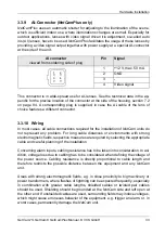
Connector ‘ALARM’
viewed from soldering side of plug
Pin
Signal
1
Input +
2
Input -
3
+5 V (max. 10 mA)
4
GND
5
Relay Y
6
Relay Z
7
Audio Output
Connector ‘IN OUT’
(NetCam6)
Connector ‘Alarm I/O’
(NetCamPlus)
3
5
7
4
6
1
2
IN
OUT
+
-
Y
Z
Alarm
Input
Control
Output
Alarm I/O Audio Power
Y
Z
+
-
Mic Spk
+
Alarm
Input
Control
Output
Audio
In/Out
Power
12V DC
GND
Summary of Contents for NetCam1
Page 1: ...NetCam1 NetCam6 NetCamPlus Manual VCS Video Communication Systems GmbH...
Page 6: ...NetCam1S NetCam6 NetCamPlus Manual VCS GmbH 6...
Page 42: ...NetCam1S NetCam6 NetCamPlus Handbuch VCS GmbH 42...
Page 80: ...Configuration Using NCTerm NetCam1S NetCam6 NetCamPlus Manual VCS GmbH 80...
Page 90: ...Appendix NetCam1S NetCam6 NetCamPlus Manual VCS GmbH 90...

