Hardware Installation
NetCam1S, NetCam6, NetCamPlus Manual, © VCS GmbH
24
3.3.5
Relay Outputs
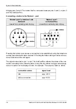
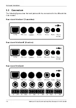
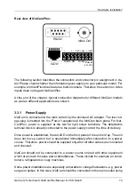
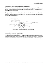
NetCam1 and NetCamPlus are equipped with one control output each, while
NetCam6 has seven control outputs total. Connection is provided at the socket la-
belled ‘Alarm’ or at the screw terminals labelled ‘OUT’ for NetCam1 and NetCam6, or
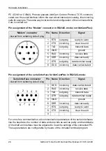
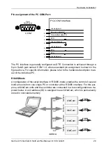
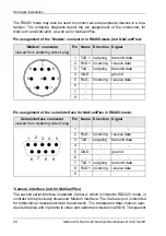
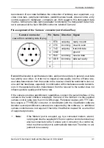
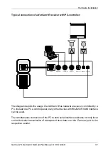
’Alarm I/O’ for NetCamPlus. The above diagrams section 3.3.4 on page 21 depict the
pin assignment of the respective connectors.
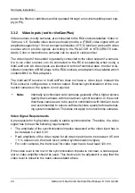
The control output is designed as a relay contact and is therefore galvanically sepa-
rated from the remaining NetCam circuitry. The relay contact is rated at max. 24 V and
0.5 A. Be careful not to connect any external voltage to the ground of the NetCam
housing, otherwise all benefits of galvanic isolation are lost.
F
Caution: To operate equipment with higher voltage or power, a respective driv-
er or power relay has to be inserted between the control output and
the unit.
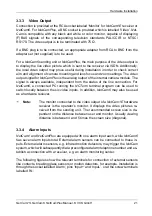
Connected devices like lamps, sirens, doors, entry control terminals, etc. can be op-
erated locally and remotely via NCTerm and ViewStation.
F
Note:
The relay outputs can be configured in a way that allows for each
alarm input to be logically connected to an relay output at the remote
site. If any input is activated or deactivated during an active connec-
tion between two NetCam units, the corresponding relay on the oppo-
site side will toggle accordingly.
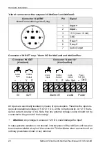
If the alarm inputs at the sender are used to automatically establish a connection, the
relay outputs at the receiver end may be configured (see section 6.5) to follow the sta-
tus of the alarming sensory device, immediately after the connection becomes active,
thus reflecting the state of the alarm input at the other end.
Note that in addition to the time required for connection establishment also the
transmission of the input state causes a certain delay. The state of the input is buff-
ered and transmitted as soon as the connection becomes active. It may take up to 2
seconds after connection establishment before the outputs accurately reflect the sta-
tus of the signalling inputs at the sender side.
Similarly, a turn-off delay has to be taken into consideration for connection tear-
down. This will ensure that commands which affect the status of the remote outputs
are correctly transmitted before the connection ends. A disconnect command should
be delayed by at least 100ms after any change in a remote relay output.
Summary of Contents for NetCam1
Page 1: ...NetCam1 NetCam6 NetCamPlus Manual VCS Video Communication Systems GmbH...
Page 6: ...NetCam1S NetCam6 NetCamPlus Manual VCS GmbH 6...
Page 42: ...NetCam1S NetCam6 NetCamPlus Handbuch VCS GmbH 42...
Page 80: ...Configuration Using NCTerm NetCam1S NetCam6 NetCamPlus Manual VCS GmbH 80...
Page 90: ...Appendix NetCam1S NetCam6 NetCamPlus Manual VCS GmbH 90...


