Configuration Using NCTerm
NetCam1S, NetCam6, NetCamPlus Manual, © VCS GmbH
58
•
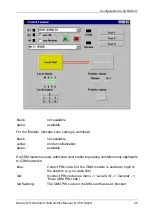
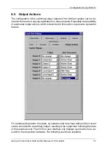
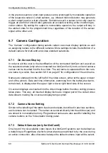
Connection: State of the ISDN, Modem, or GSM connection. Example: An active
connection is indicated by a lamp connected to one of the outputs.
•
Camera 1...6: Selection of a camera. Example: A connected camera is powered
on demand, i.e. the camera is only powered when selected.
•
Local or remote input 0...6: State of each alarm input. Example: Connection of
an external warning device (lamp, siren, beeper, etc.) which should follow an ex-
ternal alarm sensor. Also, a cross-connection of inputs and outputs in NetCam to
NetCam connections can be configured, e.g. having the local outputs follow the
remote inputs.
•
Alarm source: Internal alarm sources such as video-alarm, ISDN-alarm, modem-
alarm and motion detection. Example: Connect an external beeper to signal mo-
tion detection.
The right hand column in the configuration dialog depicted above concerns automat-
ed output actions when the active connection ends. All actions on disconnect will
override any other pending output states. For example, an activated output operating
in monostable mode (discussed below) will be preempted, if the idle state has been
programmed after disconnect. The respective idle or active state of an output is de-
fined by the dialog which is described in the next section.
6.6
Output Configuration
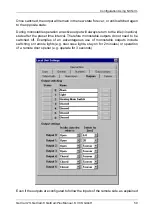
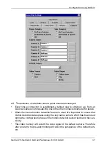
Configuration of the outputs encompasses the setting of names and the programming
of the switching behavior. In addition outputs may also be operated manually. The
number of available outputs displayed in the user interface depends on the connected
NetCam system. The configuration is stored in nonvolatile memory.
The display on the left hand side reflects the state of each of the outputs and is equiv-
alent to the display on the main window of NCTerm. The name shown to the right of
the status display can be changed by directly typing into the edit box. Given names
are typically chosen to identify connected external devices in order to aid the user.
Outputs are operated by clicking on the status display, which also serves as a button.
Note that the current status of the switching outputs is not stored. After power-up all
outputs are in the configured idle state.
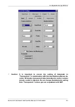
The lower half of the configuration panel allows for the setting of the switching char-
acteristics of each individual output. This includes the definition of the idle state, i.e.
relay open or closed in idle state, and selection of mono- or bistable operation.
When an output is programmed to be bistable, both states, open or closed, are stable.
Summary of Contents for NetCam1
Page 1: ...NetCam1 NetCam6 NetCamPlus Manual VCS Video Communication Systems GmbH...
Page 6: ...NetCam1S NetCam6 NetCamPlus Manual VCS GmbH 6...
Page 42: ...NetCam1S NetCam6 NetCamPlus Handbuch VCS GmbH 42...
Page 80: ...Configuration Using NCTerm NetCam1S NetCam6 NetCamPlus Manual VCS GmbH 80...
Page 90: ...Appendix NetCam1S NetCam6 NetCamPlus Manual VCS GmbH 90...

