


5 Display and Configuration Interface
Varec, Inc.
79
6. Select Analog Output #1.
7. Monitor the 4-20 mA meter, and Press the E button.
8. Enter the value from the 4-20 mA Meter into the Cal. Point #1.
9. Repeat this process for calibration points 2 through 5.
10. Press the C button twice to exit to the main menu
11. Select Analog Output from the main Menu on the 2920.
12. Select Analog Output #1.
13. Scroll to the Commands menu.
14. Scroll the menu to the Value parameter.
15. Enter values 0 to 100 (percent) and verify the measurement on the 4-20 mA Meter:
0.0 = 4.00 +/- 0.01
25.0 = 8.00 +/- 0.01
50.0 = 12.00 +/- 0.01
75.0 = 16.00 +/- 0.01
100.0 = 20.00 +/- 0.01
Output Calibration of Channel 2
1. Connect terminals A+24V and AO2+.
2. Connect a calibrated 4-20 mA Meter to terminals AO2- & AI COM.
3. If the 24VDC Output Power Supply is turned off (default), turn it on using the following
steps:
a. Select the Basic Setup from the main Menu on the 2920.
b. Scroll to the Config Params menu.
c. Scroll to the Control parameter.
d. Set the control parameter to On.
4. Select Calibration from the main Menu on the 2920.
5. Select Analog Output.
6. Select Analog Output #2.
7. Monitor the 4-20 mA meter, and Press the E button.
8. Enter the value from the 4-20 mA Meter into the Cal. Point #1.
9. Repeat this process for calibration points 2 through 5.
10. Press the C button twice to exit to the main menu
11. Select Analog Output from the main Menu on the 2920.
12. Select Analog Output #2.
13. Scroll to the Commands menu.
14. Scroll the menu to the Value parameter.
Summary of Contents for 2920
Page 2: ......
Page 16: ...2920 Float Tape Transmitter 1 Introduction 6 Installation and Operations Manual...
Page 114: ...2920 Float Tape Transmitter 6 Bi Phase Mark 104 Installation and Operations Manual...
Page 120: ...2920 Float Tape Transmitter 7 MODBUS 110 Installation and Operations Manual...
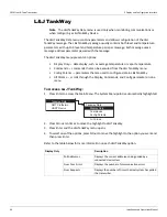
Page 126: ...2920 Float Tape Transmitter 9 L J TankWay 116 Installation and Operations Manual...
Page 158: ...2920 Float Tape Transmitter 14 Ordering Information 148 Installation and Operations Manual...
Page 193: ......