


11 Configuration & Calibration — Level, Limits, and Outputs
Varec, Inc.
125
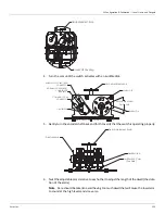
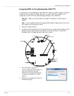
1. Remove the 2920 FTT cover.
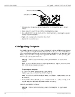
2. Connect a laptop computer running ViewRTU software to the RS-232 connector (J6) on the
communications circuit board. The following figure shows the connector.
Note
Input and output terminals are identified in a table on page 35.
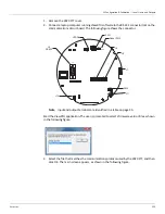
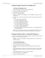
Start the ViewRTU application. The user is prompted to select a firmware version file as shown
in the following figure.
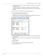
3. Select the file that matches the communications protocol used by the 2920 FTT, and then
click OK. The main screen appears, as shown in the following figure.
RESET
LED
SW1
J6
J8
SW6
J9
J7
J12
J11
SW2
J6
RS-232
J12
SW6
J11
J7
J9
J8
Reset SW2
SW1
LED D4
Summary of Contents for 2920
Page 2: ......
Page 16: ...2920 Float Tape Transmitter 1 Introduction 6 Installation and Operations Manual...
Page 114: ...2920 Float Tape Transmitter 6 Bi Phase Mark 104 Installation and Operations Manual...
Page 120: ...2920 Float Tape Transmitter 7 MODBUS 110 Installation and Operations Manual...
Page 126: ...2920 Float Tape Transmitter 9 L J TankWay 116 Installation and Operations Manual...
Page 158: ...2920 Float Tape Transmitter 14 Ordering Information 148 Installation and Operations Manual...
Page 193: ......