


4 Wiring
Varec, Inc.
27
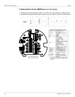
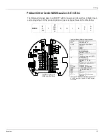
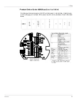
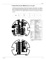
At the top of every wiring diagram is the list for that particular order code.
Here’s a breakdown of what each column means:
1. Name of the product
2. Approval (AT = ATEX/IECEx, FC = cFMus -40°C, FM = -20/25°C cFMus)
3. Power (1 = DC, 2 = AC)
4. Communications board (BP = Bi-Phase Mark, MB = RS-485 MODBUS, MS = Mark/Space, LJ
= L&J TankWay)
5. Limit Switch (Number of limit switches: 0 = 0 LS, 1 = 2 LS, 2 = 4 LS)
6. Limit Switch Range (N = NA if column d = 0, A = 0-25 ft LS range, B = 0-50 ft LS range, C =
0-100 ft LS range, D = 0-7.5 m LS range, E = 0-15 m LS range, F = 0-30 m LS range)
7. Additional Digital Inputs/Outputs (0 = no additional DIDO, 1 = additional DIDO)
8. Analog Inputs/Outputs (N = no analog I/O, A = analog input, B = analog outputs, C = analog
inputs and outputs)
9. HART (0 = Explosion-proof HART, 1 = I.S. HART)
10. Display Orientation (A = forward facing display, B = backwards facing display, C = right-side
facing display)
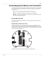
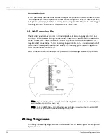
Explosion Proof and I.S. HART
Varec optionally provides an Intrinsically Safe (I.S.) HART I/O to be used with I.S. field devices,
such as radars and temperature transmitters. I.S. HART models have a separate I.S. junction
box for field terminations. Models that do not have I.S. HART have explosion-proof HART I/O
denoted as
HART+
and
HART-
on TB5 on the main terminal board with the display (as shown
on the left below). Explosion-proof I/O can only be used with explosion-proof field devices. I.S.
HART models have
L
and
H
terminals on TB5 (as shown on the right below). The L & H terminals
are for future functionality and are not used at this time.
1
2 (aa)
3 (b)
4 (cc)
5 (d)
6 (e)
7 (f)
8 (g)
9 (h)
10 (i)
N2920
AT
FC
FM
1
BP
MB
MS
LI
1
A
B
C
D
E
F
1
N
A
B
C
0
1
A
B
C
Summary of Contents for 2920
Page 2: ......
Page 16: ...2920 Float Tape Transmitter 1 Introduction 6 Installation and Operations Manual...
Page 114: ...2920 Float Tape Transmitter 6 Bi Phase Mark 104 Installation and Operations Manual...
Page 120: ...2920 Float Tape Transmitter 7 MODBUS 110 Installation and Operations Manual...
Page 126: ...2920 Float Tape Transmitter 9 L J TankWay 116 Installation and Operations Manual...
Page 158: ...2920 Float Tape Transmitter 14 Ordering Information 148 Installation and Operations Manual...
Page 193: ......