


11 Configuration & Calibration — Level, Limits, and Outputs
Varec, Inc.
123
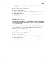
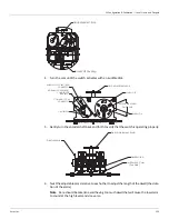
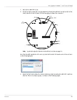
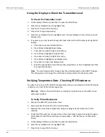
4. Turn the cam until the switch activates with an audible click.
5. Gently turn the encoder shaft back and forth to verify that the switch is operating properly.
6. Twist the adjustable cams relative to each other to adjust the length of the dwell (the dura-
tion of the alarm).
Note
Care should be taken to avoid having too much dwell that will cause the low alarm
to sound at the high levels and vice versa.
Field Adjustment Knob
Drive Shaft Coupling
ADJUSTABLE ALARM
DWELL TIME
ALARM ON
ALARM OFF
FIELD ADJUSTMENT KNOB
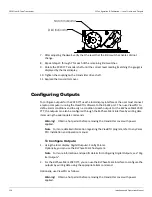
NORMALLY CLOSED (NC2)
COMMON (COM)
CONNECTOR
(UNUSED)
CONNECTOR
NORMALLY OPEN (NO3)
CONNECTOR
LIMIT SWITCH
Dial Indicator
Field Adjustment Knob
(Far Side)
Limit Switch Cam
Limit Switch
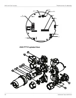
Summary of Contents for 2920
Page 2: ......
Page 16: ...2920 Float Tape Transmitter 1 Introduction 6 Installation and Operations Manual...
Page 114: ...2920 Float Tape Transmitter 6 Bi Phase Mark 104 Installation and Operations Manual...
Page 120: ...2920 Float Tape Transmitter 7 MODBUS 110 Installation and Operations Manual...
Page 126: ...2920 Float Tape Transmitter 9 L J TankWay 116 Installation and Operations Manual...
Page 158: ...2920 Float Tape Transmitter 14 Ordering Information 148 Installation and Operations Manual...
Page 193: ......