


11 Configuration & Calibration — Level, Limits, and Outputs
Varec, Inc.
127
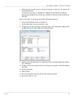
5. Define the alarm conditions that can be used for outputs. At minimum, set values for the
following parameters:
CritLowLevel, AdvLowLevel, AdvHighLevel, CritHighLevel, LDeadband, CritLowTemp,
AdvLowTemp, AdvHighTemp, CritHighTemp, TDeadband, MinLevel, MaxLevel, MinTemp,
MaxTemp
Refer to “Tank Data” for information about the TANK point (parameter).
6. Set any other TANK parameters as appropriate.
7. Click the Exit button to return to the main screen.
8. Using the icons or the Point menu, select the DO point. The DO dialog box appears, show-
ing data items that can be modified in the following figure.
9. Assign a control & activation event to each direct output by defining parameters DO1As-
sign – D04Assign.
10. To make a relay active at system startup, set the appropriate register in the DOPwrUpState
parameter.
11. Click the Exit button.
12. Close ViewRTU.
13. Disconnect the laptop computer cable from the RS-232 connector.
14. Replace the 2920 FTT cover.
Summary of Contents for 2920
Page 2: ......
Page 16: ...2920 Float Tape Transmitter 1 Introduction 6 Installation and Operations Manual...
Page 114: ...2920 Float Tape Transmitter 6 Bi Phase Mark 104 Installation and Operations Manual...
Page 120: ...2920 Float Tape Transmitter 7 MODBUS 110 Installation and Operations Manual...
Page 126: ...2920 Float Tape Transmitter 9 L J TankWay 116 Installation and Operations Manual...
Page 158: ...2920 Float Tape Transmitter 14 Ordering Information 148 Installation and Operations Manual...
Page 193: ......