


4 Wiring
Varec, Inc.
19
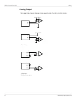
Terminating System Wiring at the Transmitter
This section provides field wiring termination information for the 2920 FTT, including junction
box terminal connections for communications, RTD input, discrete inputs, contact outputs,
and input power
Note
Varec recommends using 18 AWG shielded twisted pair wiring.
Caution!
Use supply wires suitable for 105°C above surrounding ambient.
Attention!
Utiliser des fils d'alimentation qui conviennent a une temperature de 105°C
au-dessus de la temperature ambiante.
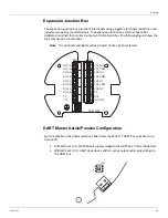
Junction Box Terminals
All wiring from the 2920 FTT is terminated at one or more junction boxes connected to the
transmitter housing.
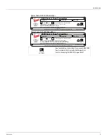
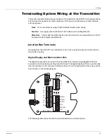
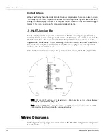
Digital Display and Main Junction Box
The digital display and main junction box provides 18 terminals using pluggable terminal
connectors and includes two earth ground terminals. The digital display and main junction box
also incorporates an LCD and user interface buttons. The terminal board for the main junction
box is shown in the following figure.
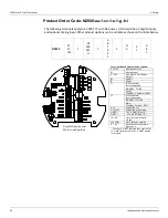
The following table shows the Main Junction Board terminal descriptions.
T1
T2
T3
T4
T5
T6
T7
T8
TB1
TB2
TB3
B +
C 1
C 2
B -
RTD A
RTD B
RTD C
DI 2
DICOM
DI 1
08-013204
L
H
R DISPL
GND
Summary of Contents for 2920
Page 2: ......
Page 16: ...2920 Float Tape Transmitter 1 Introduction 6 Installation and Operations Manual...
Page 114: ...2920 Float Tape Transmitter 6 Bi Phase Mark 104 Installation and Operations Manual...
Page 120: ...2920 Float Tape Transmitter 7 MODBUS 110 Installation and Operations Manual...
Page 126: ...2920 Float Tape Transmitter 9 L J TankWay 116 Installation and Operations Manual...
Page 158: ...2920 Float Tape Transmitter 14 Ordering Information 148 Installation and Operations Manual...
Page 193: ......