


5 Display and Configuration Interface
Varec, Inc.
77
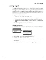
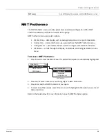
4. Select either Analog Out #1 or Analog Out #2.
Note
The parameters for Analog Out #1 and Analog Out #2 are identical. However, each
Analog Out can be configured differently. Analog Out #1 is used as an example below.
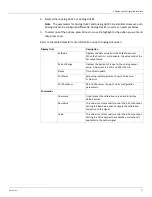
5. To select one of the options, press Minus to move the highlight to the option you want and
then press Enter.
Refer to the table below for more information on each Analog Out option.
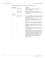
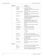
Display Only
Description
RefValue
Displays the data value from the PntRef data item.
When the Control is set to enable, this value control the
AO output value.
Percent Range
Displays the percent of range for the analog output
value. A 0 percent is 4 mA, and 100 is 20 mA.
Elapse
Time of last update.
Pnt Status
Byte value indicating status of point. Values are:
0: No error
Pnt CheckSum
CRC-16 Checksum of point's static configuration
parameters.
Commands
Command
Used to reset the calibration curve back to factory
default values.
Raw Value
This value is set to manually control the 4-20 mA output.
Setting the Raw Value does not apply the calibration
correction to the signal.
Value
This value is set to manually control the 4-20 mA output.
Setting the Value applies the calibration correction (if
available) to the output signal.
Summary of Contents for 2920
Page 2: ......
Page 16: ...2920 Float Tape Transmitter 1 Introduction 6 Installation and Operations Manual...
Page 114: ...2920 Float Tape Transmitter 6 Bi Phase Mark 104 Installation and Operations Manual...
Page 120: ...2920 Float Tape Transmitter 7 MODBUS 110 Installation and Operations Manual...
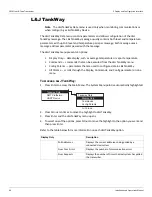
Page 126: ...2920 Float Tape Transmitter 9 L J TankWay 116 Installation and Operations Manual...
Page 158: ...2920 Float Tape Transmitter 14 Ordering Information 148 Installation and Operations Manual...
Page 193: ......