


Installation and maintenance instructions ecoTEC plus 937 0020031552_06
53
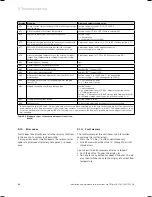
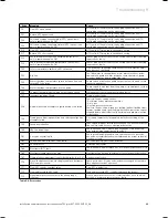
8.2
Maintaining the compact thermal module
8.2.1
Removing the compact thermal module
a
Danger!
Risk of burns caused due to hot compo-
nents.
The compact thermal module, all water-carry-
ing parts and the heating water may become
hot and cause burns or scalding.
Only work on these components if these
parts have cooled down.
The thermo-compact module consists of the burner, the
fan, the gas valve and the gas supply (mixture pipe).
Proceed as follows to remove it:
Switch the combi boiler off.
Isolate the power supply from the combi boiler.
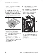
Remove the bottom cover (if fitted) of the combi
boiler by releasing both the spring clips and lowering
the back of the bottom cover downwards.
Pull the bottom cover slightly towards the back
Remove the bottom cover from the unit.
Turn the stop valve off.
Turn the stop valves of the central heating off.
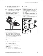
Release the screw and the spring clips on the front
panel located under the front of the unit.
2
3
1
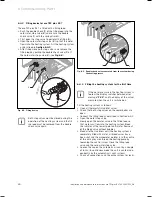
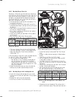
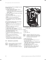
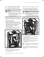
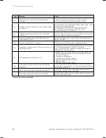
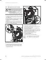
Fig. 8.2 Removing the air inlet pipe
Remove the front of the of the unit by pulling the
bottom edge forwards and lifting slightly.
Lower the electronic box.
>
>
>
>
>
>
>
>
>
>
>
Unscrew the screw (
2
) and remove the air inlet pipe
(
1
).
Separate the gas supply line (
3
) from the gas valve.
Make sure that the corrugated gas pipe does not
twist by holding the flattened end of the pipe with an
open ended spanner whilst you release the cap nut.
b
Caution!
Risk of damage to the corrugated gas pipe.
The corrugated gas pipe may become dam-
aged if subjected to stress.
Do not suspend the compact thermal mod-
ule by the flexible corrugated gas pipe.
10
11
9
8
4
5
6
7
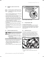
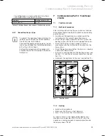
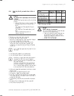
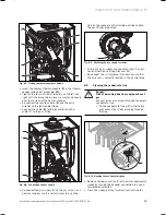
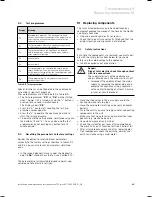
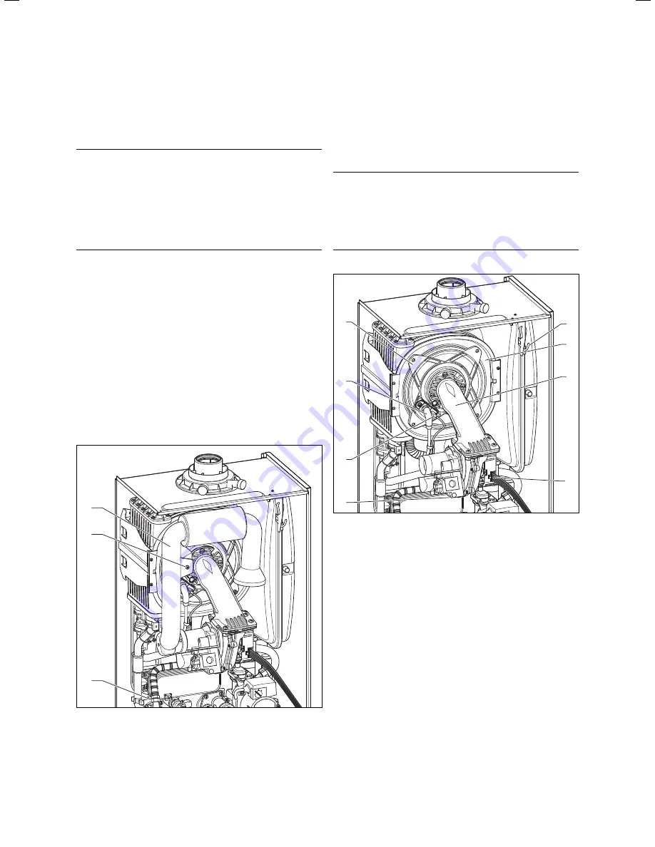
Fig. 8.3 Removal of the thermo-compact module
Pull the ignition cable (
5
) and the earth wire (
6
) off
the ignition electrode.
Unscrew the four nuts (
4
) from the burner door.
Pull the two electrical connections (
7
and
8
) off the
fan and the gas valve.
Pull the burner, gas valve and fan assembly (
9
) for-
wards off the integral condensation heat-
exchanger (
10
).
i
You can hang the thermo-compact module on
the hook (
11
) whilst you perform the mainte-
nance work.
After removing the thermo-compact module clean
the components in accordance with the following
description.
>
>
>
>
>
>
>
>
Inspection and maintenance 8
Summary of Contents for ecoTEC plus 937
Page 1: ...For the heating engineer Installation and maintenance instructions GB IE ecoTEC plus 937 VUI...
Page 74: ...74 Installation and maintenance instructions ecoTEC plus 937 0020031552_06...
Page 76: ...76 Installation and maintenance instructions ecoTEC plus 937 0020031552_06...
Page 77: ...Installation and maintenance instructions ecoTEC plus 937 0020031552_06 77...
Page 78: ......
Page 79: ......
Page 80: ...0020031552_06 GBIE 102010 Subject to alterations...


