Installation and maintenance instructions ecoTEC plus 937 0020031552_06
47
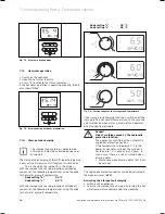
The symbol " “ is displayed.
Turn the hot water temperature control knob to the
temperature you require.
Press "
i
" to activate the status indicator.
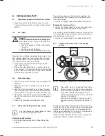
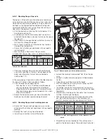
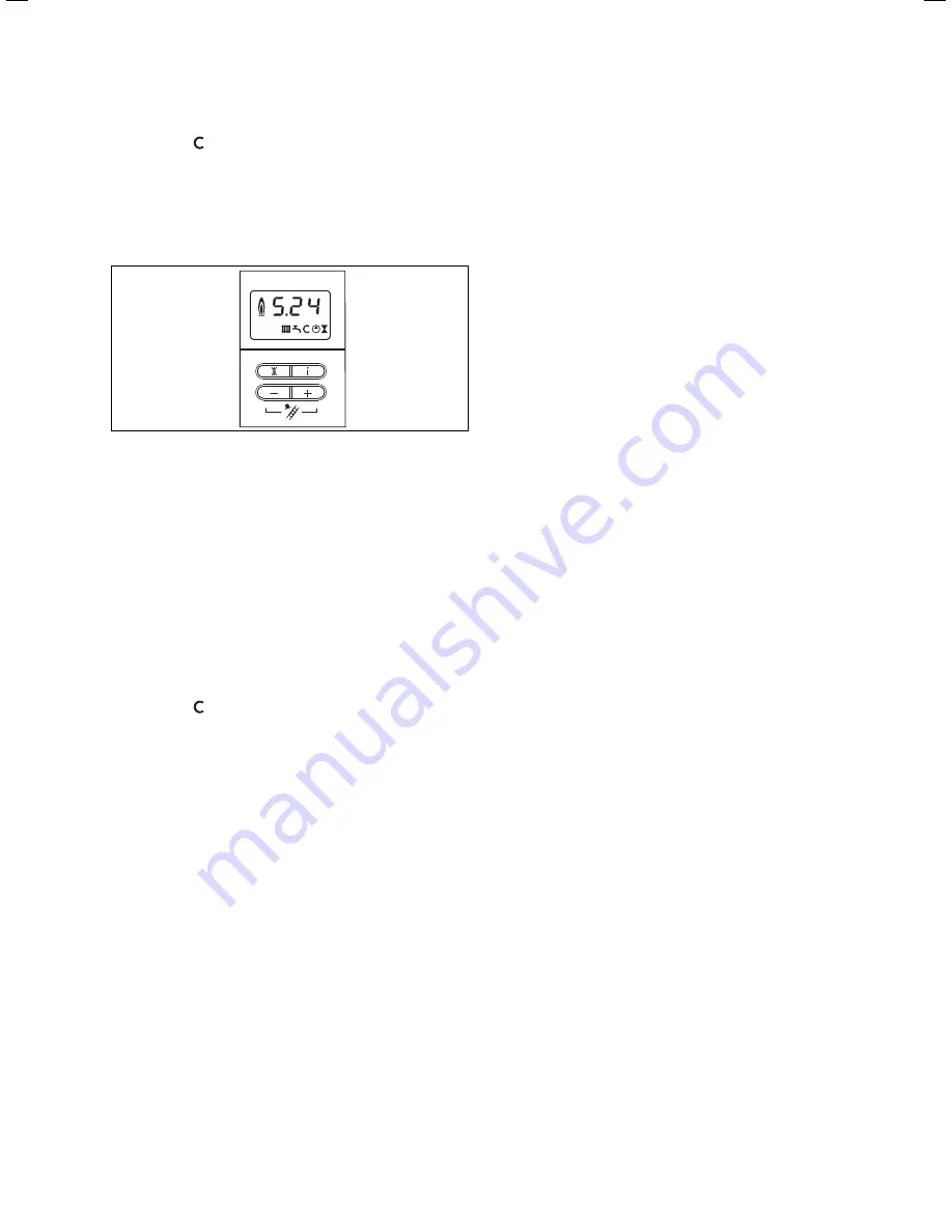
During the storage tank charging the display shows
"
S.24
“.
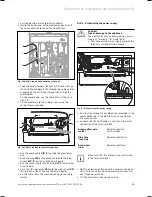
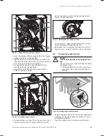
Fig. 7.5 Display during storage tank charging
i
When operating the appliance in the winter,
the tank charging function is limited in order
to prevent the heating installation from cool-
ing down. The maximum tank charging time is
set to 45 minutes by the manufacturer. Your
heating engineer can alter this setting via
diagnostic point "
d.75
".
De-activating the storage tank charging
De-activate the storage tank charging by turning the
hot water temperature control knob fully anti-clock-
wise.
The symbol " “ disappears.
Then set the desired hot water temperature. The unit
now operates in the through-flow principle, the stor-
age tank is not held at temperature.
7.1.5
Conclusive flushing of the heating system
("hot")
Allow the appliance to run until both the appliance
and the heating system have reached their operating
temperature.
Check the heating system for leaks.
Connect a hose to the drain valve which is located at
the lowest position in the heating system.
Shut off the appliance, open the drain valve and all
vent valves on the radiators and allow the water to
flow out of the heating system and the combi boiler
quickly and fully.
Close the drain valve.
Re-fill the heating system with water as described in
Section 6.4.3.
Drain water out of the system until a system pressure
of 1.0 bar is reached. (The ideal measured value on
the pressure gauge is 0.5 bar plus an extra amount
>
>
>
>
>
>
>
>
>
>
>
corresponding to the highest point of the system
above the combi boiler. A height of 10 m corresponds
to a pressure increase on the pressure gauge of
around 1 bar. The pressure must not be less than 1 bar
on any installation.)
If the system is to be protected by an inhibitor, it
should be added at this stage in accordance with the
manufacturer's instructions.
Further information can be obtained from Sentinel,
Betz Dearborn Ltd., Tel.: 0151 420 9595, or from Fer-
nox, Alpha–Fry technologies, Tel.: 0870 8700362.
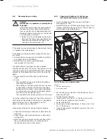
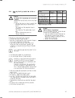
Re-fit the enclosure of the combi boiler (see Section
6.10).
Fit the base cover to the combi boiler and shift load
storage tank by pushing the front edge of the cover
into the retaining tag on the front lower edge of the
unit framework.
Carefully push the base cover upwards until the
spring clips on the side of the unit engage.
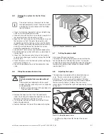
It may be necessary to modify the base cover by
removing the easily removable breakaway sections.
7.2 Briefing
users
i
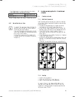
When installation is complete, attach the sup-
plied sticker (item no. 835 593) in the user’s
language to the front of the appliance.
Set the controller for the maximum radiator tempera-
ture to the required temperature.
Set the controller for the maximum hot water tem-
perature to the required temperature.
Instruct the operator in the safe and efficient opera-
tion of the combi boiler, paying particular attention to
the functions of:
the ON/OFF switch of the combi boiler,
the controller for the maximum radiator tempera-
ture,
the controller for the maximum hot water temper-
ature,
the pressure gauge.
Make the operator acquainted with the operation of
any external controllers.
Explain to the operator the importance of regular
maintenance by a competent heating engineer.
It is strongly recommended that a maintenance con-
tract be taken out to ensure regular maintenance.
Further information can be obtained from Vaillant
Service Solutions (0870 6060 777).
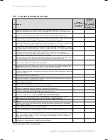
Enter the operating pressure of the central heating
system, the heat input (in kW) and the temperature
difference between the flow and return in the Bench-
mark gas boiler commissioning checklist.
If the appliance is not installed and commissioned in
accordance with manufacturer's instructions this can
lead to invalidation of the guarantee (Note: Your legal
rights remain unaffected by this.)
>
>
>
>
>
>
>
–
–
–
–
>
>
>
Commissioning Part II: Functional checks 7
Summary of Contents for ecoTEC plus 937
Page 1: ...For the heating engineer Installation and maintenance instructions GB IE ecoTEC plus 937 VUI...
Page 74: ...74 Installation and maintenance instructions ecoTEC plus 937 0020031552_06...
Page 76: ...76 Installation and maintenance instructions ecoTEC plus 937 0020031552_06...
Page 77: ...Installation and maintenance instructions ecoTEC plus 937 0020031552_06 77...
Page 78: ......
Page 79: ......
Page 80: ...0020031552_06 GBIE 102010 Subject to alterations...

