Installation and maintenance instructions ecoTEC plus 937 0020031552_06
41
6.5
Flushing the system for the first time
("cold")
i
The entire heating system must be flushed
through completely at least twice: once cold
and once hot, in accordance with the follow-
ing instructions.
Check if all radiator thermostat valves and both stop
valves on the combi boiler are open.
Connect a hose to the drain valve which is located at
the lowest position in the heating system.
Open the 1/2“ drain valves and all the bleed valves on
the radiators so that the water flows quickly and
completely out of the heating system and the combi
boiler, in order to remove the contamination caused
during the installation out of the heating system
before the combi boiler is started up.
Close the 1/2” drain valves and radiator bleed vavles.
Re-fill the heating system with water as described in
Section 6.4.3.
Check that the pressure relief valve in the heating
system is functioning correctly by turning the handle
on the valve.
Check the pressure in the heating system and top up
with water if necessary.
Close the filling loop valve and the cold water stop
valve.
6.6
Filling the condensate drain trap
a
Danger!
Risk of poisoning from escaping exhaust
gas.
If the appliance is operated with an empty
condensate trap, exhaust gas may escape and
cause poisoning.
Before initial operation, fill the condensate
trap with water as follows.
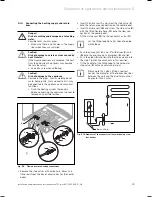
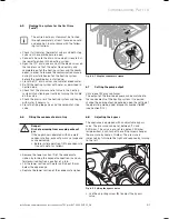
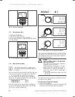
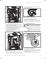
Remove the lower section (
1
) of the condensate
siphon by turning the bayonet connection in a coun-
terclockwise direction a quarter of a turn.
Fill the lower section with water until about 10 mm
below the upper edge.
Replace the lower section of the condensate siphon.
>
>
>
>
>
>
>
>
>
>
>
>
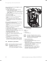
1
Fig. 6.4 Filling the condensate siphon
6.7
Setting the pump output
Only in ecoTEC plus appliances:
The output of the two-speed pump can be matched to
the requirements of the heating system. If required,
change the pump output, depending upon the setting of
the operating mode, under diagnostic number "
d.19
“
(see Section 9.1.2).
6.8 Adjusting
the
bypass
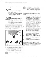
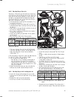
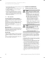
The appliance is equipped with an adjustable bypass
valve. The pressure can be set between 170 and
350 mbar. The valve is pre-set to approx. 250 mbar
(mid-position). Each turn of the setting screw changes
the pressure by approx. 10 mbar. The pressure is
increased by turning to the right and reduced by turning
to the left.
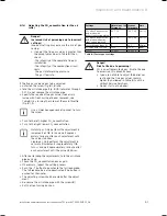
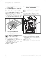
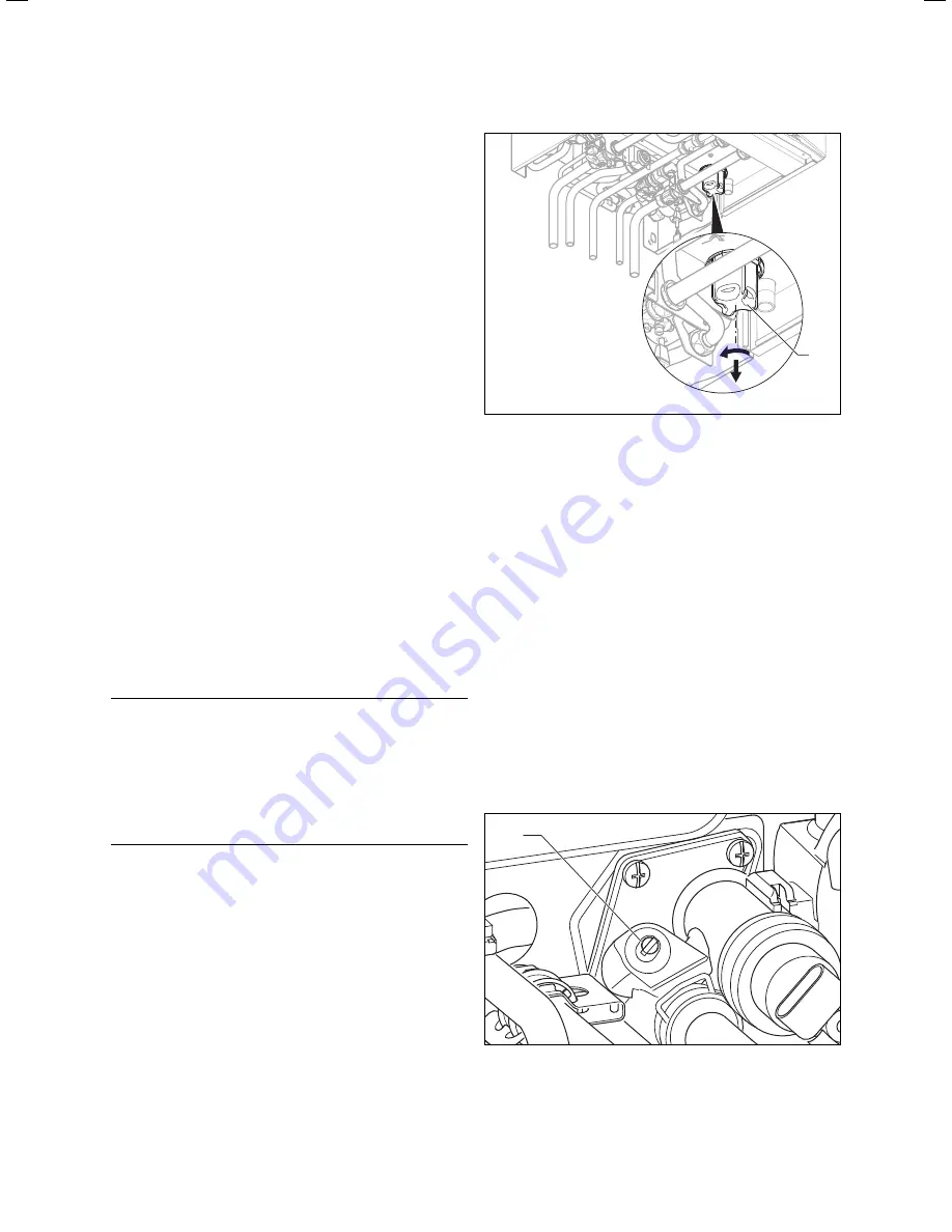
1
Fig. 6.5 Setting the bypass valve
Use the adjusting screw
(1)
to adjust the bypass
valve.
>
Commissioning, Part I 6
Summary of Contents for ecoTEC plus 937
Page 1: ...For the heating engineer Installation and maintenance instructions GB IE ecoTEC plus 937 VUI...
Page 74: ...74 Installation and maintenance instructions ecoTEC plus 937 0020031552_06...
Page 76: ...76 Installation and maintenance instructions ecoTEC plus 937 0020031552_06...
Page 77: ...Installation and maintenance instructions ecoTEC plus 937 0020031552_06 77...
Page 78: ......
Page 79: ......
Page 80: ...0020031552_06 GBIE 102010 Subject to alterations...


