52
Installation and maintenance instructions ecoTEC plus 937 0020031552_06
8.1.5
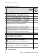
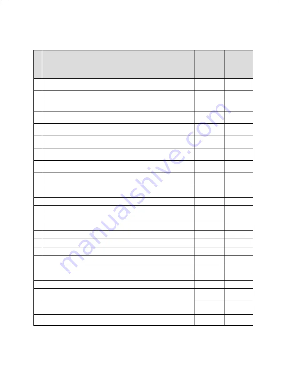
Inspection and maintenance work steps
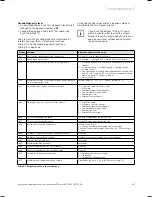
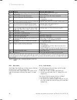
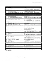
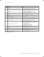
No. Activity
Column 1
Inspection must
be carried out
each year
Column 2
Maintenance
must be carried
out at regular
intervals – but
no longer than
5 years
1
Check the air flue gas installation for leaks and for proper fixation and ensure it is not
blocked or damaged and is fitted correctly, complying with the relevant installation instruc-
tions.
x
x
2
Carry out a general inspection of the boiler for dirt and dust and clean as necessary.
x
x
3
Visually inspect the complete heat engine for its general condition and for signs of corrosion,
sooting or other forms of damage. If damage is evident proceed to column 2.
x
x
4
Measure the gas flow rate during operation with maximum load (section 5.9.2). If the gas flow
rate complies to the Table 5.1 continue with column 1, if not proceed to column 2.
x
x
5
Check the gas inlet working pressure (section 5.9.3) operation with maximum load. If the gas
inlet working pressure complies to the Table 5.2 continue with column 1, if not proceed to col-
umn 2.
x
x
6
Check combustion by measuring CO, CO
2
and CO/CO
2
. If the values are outside the
tole rances of Table 7.1 proceed to maintenance column 2. You must not proceed with the
maintenance if a new burner door seal kit is not available.
x
7
Isolate the boiler from the power mains. Check whether the electrical plug connections and
the other electrical connections are fitted tightly and correct them if necessary.
x
x
8
Close the gas isolation valve and the service valves.
x
9
Dump the pressure in the boiler on the water side (observe pressure gauge) and check the
charge pressure of the expansion vessel of the boiler. Top up if necessary.
x
10
Check the charge pressure of the expansion vessel of the shift load storage tank. If required,
correct the pressure.
x
x
11
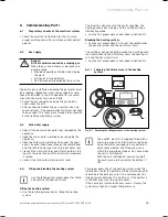
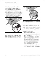
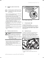
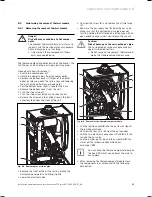
Remove the compact thermal module.
x
12
Check the integrity of all combustion circuit seals, especially the burner door seal. If there are
any damages repair them before proceeding.
x
13
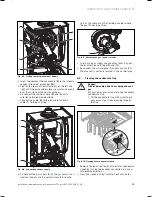
Clean the heat exchanger.
x
14
Check whether the burner is dirty and clean it if necessary.
x
15
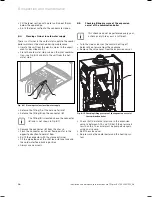
Check the condensate siphon in the boiler, clean and fill if necessary.
x
x
16
Check the condensate ducts in the boiler and clean if necessary.
x
x
17
Install the compact thermal module.
Caution: Use new seals and nuts!
x
18
Open the service valves and fill up the boiler/appliance to approximately 1.0 - 2.0 bar
(depending on the static height of the system). Start the bleeding program P.0.
x
19
Open the gas isolation valve, reconnect the boiler with the power mains and switch on the
boiler.
x
x
20
Perform a test operation of the boiler and heating installation, including water heating and
bleed again if necessary.
x
x
21
Check visually the ignition and burner performance.
x
x
22
Check the boiler for leaks of any kind (gas, flue gas, water, condensate) and rectify as neces-
sary.
x
x
23
If you had problems with the CO, CO
2
, CO/CO
2
-values in Step 6 before the maintenance, check
them again now (see Table 7.1). If they are outside of the tolerances of Table 7.1 make an
adjustment, see section 7.1.4.
x
24
Complete the gas commission checklist (benchmark book).
x
x
Table 8.2 Inspection and maintenance steps
8 Inspection and maintenance
Summary of Contents for ecoTEC plus 937
Page 1: ...For the heating engineer Installation and maintenance instructions GB IE ecoTEC plus 937 VUI...
Page 74: ...74 Installation and maintenance instructions ecoTEC plus 937 0020031552_06...
Page 76: ...76 Installation and maintenance instructions ecoTEC plus 937 0020031552_06...
Page 77: ...Installation and maintenance instructions ecoTEC plus 937 0020031552_06 77...
Page 78: ......
Page 79: ......
Page 80: ...0020031552_06 GBIE 102010 Subject to alterations...

