Installation and maintenance instructions ecoTEC plus 937 0020031552_06
39
6 Commissioning,
Part
I
6.1
Preparatory checks of the electrical system
Check the electrical installation for short circuits,
proper earthing and earth resistance and for correct
polarity.
6.2 Gas
supply
a
Danger!
Risk of explosion caused by escaping gas.
When the gas line is bled, gas may leak and
possibly ignite.
Provide adequate ventilation whilst doing
the work.
Extinguish all naked flames.
Do not smoke while bleeding the gas line.
The entire gas installation including the gas meter must
be inspected, checked for leaks and purged in accord-
ance with BS 6891. In the Irish Republic (IE) in accord-
ance with the current version of IS 813.
Purge the gas supply by opening the gas isolator
valve under the unit.
After purging re-tighten the gas isolator valve and
check for leaks. (The combi boiler itself does not need
to be purged.) This takes place through the automatic
burner ignition monitoring system.
6.3 Cold
water
supply
Open all the domestic hot water taps supplied by the
appliance.
Open the mains water isolating valve supplying the
appliance.
Open the cold water isolating valve under the appli-
ance. The water then flows through the combi boiler
and the shift load storage tank to the hot water taps.
Close all the hot water taps one after the other start-
ing with the lowest one until the hot water pipework
is vented.
Check all hot and cold water pipes for leaks.
6.4
Filling and bleeding the heating system
i
Use the following test programmes for filling
and venting the heating system:
Filling the heating system
Use the test programme P.6 for filling the heating
system:
>
>
>
>
>
>
>
>
>
>
>
>
The diverter valve moves to the central position, the
heating pump is not running and the unit does not go
into heating mode.
Use the test programme as described in Section 9.2.
Bleeding the heating system
Use the test programme P.0 to vent the combi boiler,
the heating system and the hot water circuit.
The unit does not go to heating mode, the heating pump
runs intermittently and alternately vents the heating cir-
cuit and the hot water circuit.
Use the test programme as described in Section 9.2.
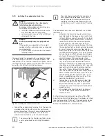
6.4.1
Checking the fill pressure in the heating
system
bar
bar
1
2
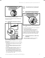
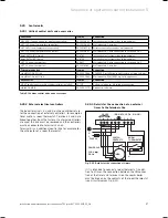
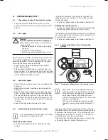
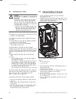
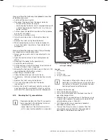
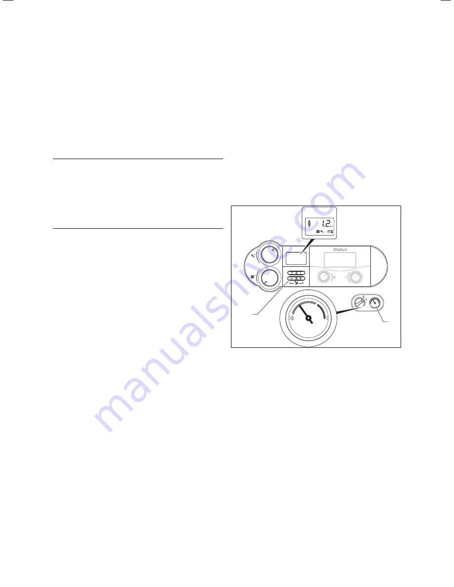
Fig. 6.1 Checking the filling pressure of the heating system
i
The ecoTEC plus 937 is supplied fitted with a
pressure gauge and a digital pressure display.
Using the pressure gauge you can perform a
quick check whether the filling pressure is
within the prescribed range or not, even when
the unit is switched off.
With the unit switched on, you can read off
the exact pressure by pushing the button "
-
"
(
2
).
For proper operation of the heating system, when the
installation is cold, the pointer on the pressure gauge (
1
)
should be in the dark-grey area. This corresponds to a
filling pressure between 1.0 and 2.0 bar. If the pointer is
in the light grey area, top up with water.
If the heating system extends over several storeys, the
system may require a higher filling pressure.
>
>
>
Commissioning, Part I 6
Summary of Contents for ecoTEC plus 937
Page 1: ...For the heating engineer Installation and maintenance instructions GB IE ecoTEC plus 937 VUI...
Page 74: ...74 Installation and maintenance instructions ecoTEC plus 937 0020031552_06...
Page 76: ...76 Installation and maintenance instructions ecoTEC plus 937 0020031552_06...
Page 77: ...Installation and maintenance instructions ecoTEC plus 937 0020031552_06 77...
Page 78: ......
Page 79: ......
Page 80: ...0020031552_06 GBIE 102010 Subject to alterations...

