


38
Installation and maintenance instructions ecoTEC plus 937 0020031552_06
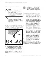
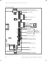
5.20.4 Optional plug-in timers by Vaillant
Further details for the connection can be found in the
relevant instructions of the accessories. The cover on
the electronics box should be replaced after all the elec-
trical connections have been made. The cover is secured
with two clips.
5.21 Thermostatic
radiator
valves
The combi boiler is equipped with an automatic adjusta-
ble by-pass valve which makes it ideal for use in sys-
tems with thermostatic radiator valves (an additional
by-pass valve is not required). In the interests of opti-
mum fuel economy, if thermostatic radiator valves are
fitted they must be used in conjunction with a interlock
block on the combi boiler. A programmable room ther-
mostat or separate timer and room thermostat will
ensure complete boiler shutdown when the heating
demand is satisfied. (The radiator in the room contain-
ing the room thermostat should not be fitted with a
TRV.)
5.22 Frost
prevention
The combi boiler is equipped with an integrated frost
protection thermostat for protecting the combi boiler.
Additional protection measures must be taken to pre-
vent external or exposed parts of the heating system
and the house, for example the fitting of an external
frost protection thermostat. This frost protection ther-
mostat should be connected to the terminals 3 and 4 on
the combi boiler, in parallel to all the other external
heating controllers.
i
External frost protection devices cannot be
used if plug-in timers are used.
5.23 Heating
pump
The combi boiler is fitted with a heating pump which is
fully wired (additional cabling is not necessary). The
pump has automatic overrun time after the combi boiler
has switched off.
5.24
Anti-cyclic "Economiser" control system
The combi boiler is fitted with an anti-cyclic controller
which ensures that energy wasting short term running
of the combi boiler cannot occur. The controller pre-
vents the combi boiler from switching on again within a
preset time period after the last switch-off of the cen-
tral heating. (Hot water preparation is not affected by
this function. Hot water can be drawn off at any time.)
i
For temporary cancellation of this switch-on
protection system, turn the main switch
ON/OFF of the combi boiler to position "
0
"
and then a few seconds later switch to posi-
tion "
l
".
5.25
Automatic pump spin control
The combi boiler is fitted with an internal controller
which causes the fitted heating pump to switch on once
in a 23 hour period and also operates the diverter valve.
This controller prevents the jamming up of these com-
ponents if the combi boiler is inactive for long periods.
This controller is inactive if the power supply to the unit
is switched off
5 Sequence of operations during installation
Summary of Contents for ecoTEC plus 937
Page 1: ...For the heating engineer Installation and maintenance instructions GB IE ecoTEC plus 937 VUI...
Page 74: ...74 Installation and maintenance instructions ecoTEC plus 937 0020031552_06...
Page 76: ...76 Installation and maintenance instructions ecoTEC plus 937 0020031552_06...
Page 77: ...Installation and maintenance instructions ecoTEC plus 937 0020031552_06 77...
Page 78: ......
Page 79: ......
Page 80: ...0020031552_06 GBIE 102010 Subject to alterations...