


ZoomSHOT 30 Fixed Camera with QUSB, QMini, QDVI System or for AV Bridge MATRIX PRO
Page 24 of 73
Z
OOM
SHOT
30
C
AMERA
-
F
IRST
T
IME
S
ET
-
UP
The ZoomSHOT 30 was designed to be very easy to use and operate. There is documentation at the back of this
manual for pin-outs for the connectors on the ZoomSHOT 30 camera and the QUSB, QMini and QDVI Interfaces.
Before Installing the Camera:
•
Choose the camera mounting location while paying close attention to camera viewing angles, lighting
conditions, possible line of site obstructions and checking for in-wall obstructions where the camera is to be
mounted. Always pick a mounting location that will optimize the performance of the camera.
•
Please locate the camera to enable easy positioning of the camera body with the ability to point down and away
from the ceiling and a bunch of fluorescent lighting cells.
Cameras generally don’t like to be swamped with
fluorescent light and very few people sit on the ceiling anyway
.
•
The Thin Profile Wall Mount for the ZoomSHOT 30 can be mounted directly to a 1-gang wall box or can be
mounted using the two (2) provided spiral drywall anchors.
•
For Power/Video and RS-232 signals, use standard Cat-5 cable (568B termination and real RJ-45 connectors)
from the EZ-POWER VIDEO and RS-232 ports on the back of the ZoomSHOT 30 to the Quick-Connect
Interface or AV Bridge MATRIX PRO. The EZ-POWER VIDEO jack on the camera is color-coded as a reminder
that there is 24 VDC power on that Cat-5 cable.
S
TEP
B
Y
S
TEP
Z
OOM
SHOT
30
S
YSTEM
I
NSTALLATION
I
NSTRUCTIONS
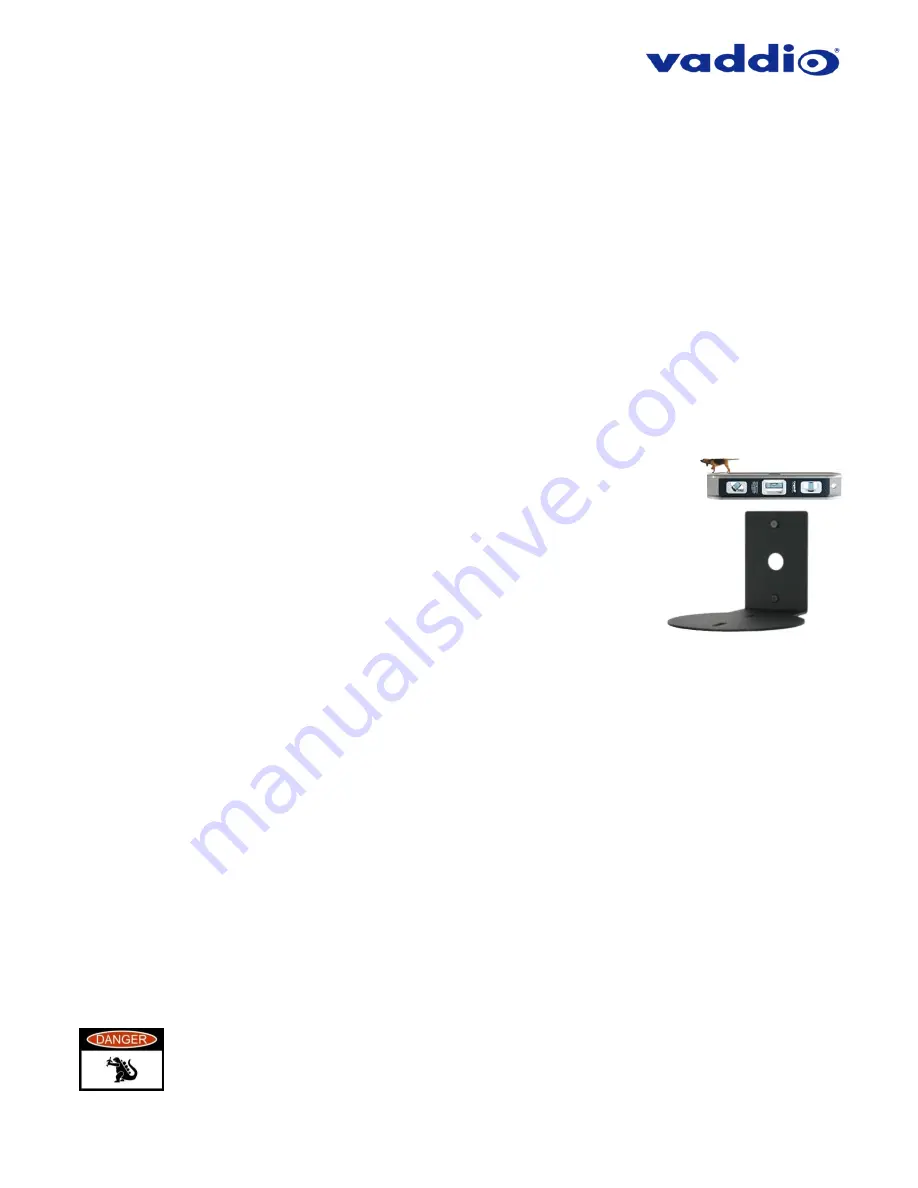
Step 1:
After determining the optimum location of the camera; route, mark and test
the two Cat-5 cables from the camera to the Quick-Connect Interface or AV Bridge
MATRIX PRO located at the table or rack. The two Cat-5 cables should feed-through
the hole located on the rear flange of the Thin Profile Wall Mount. If the bracket is to
be mounted on a 1-gang wall box, use the screws supplied with the wall box cover
plate to attach the Thin Profile Wall Mount. If mounting to the drywall with wall anchors,
use two quality wall anchors. The mount provides for easy leveling. Pull the Cat-5
cables though the wall and feed the cables through the back of the mount. Level the
mount and tighten the mounting screws.
Step 2:
Using the HD VIDEO SELECT rotary switch and CAMERA SETTINGS dip switches on the back of the
camera, set up the camera’s output resolution and functional preferences. See Table: ZoomSHOT 30 DIP Switch
Settings and
4) HD Video Select:
A rotary switch allows the user to choose the HD output video resolution and format. After setting or
changing the resolution, reboot the camera to ensure proper operation. If an unassigned rotary selection position is chosen (9,
A, B, C or D), the camera will not output video. Simply set the rotary switch to an assigned position to output video. See rotary
switch settings below.
Table: ZoomSHOT 30 VIDEO Selections
…keep these tables handy for future use.
Setting the ZoomSHOT 30 Camera:
•
Set the desired HD Resolution with the rotary selection switch. If changing the resolution, always reboot
the camera to ensure proper operation.
Note:
For systems with the Quick-Connect USB Mini, the camera must be set to 720p/59.94 (rotary
position “0”)
•
Set the IR ID (1, 2 or 3) of the camera (if it is to respond to the IR SHOT Commander Remote).
•
Set the desired image orientation (normal or flipped).
Step: 3:
Follow the sample wiring diagram for connecting the Cat-5 cables to the ZoomSHOT 30 that come in the
Quick-Start Guide that ships with your camera
,
but read and understand the rest of these instructions - especially
the next note.
NOTE:
Check all Cat-5 cables for continuity in advance of the final connection. Label the Cat-
5 cables. Plugging the EZ-POWER VIDEO cable into the wrong RJ-45 may cause damage to
the camera system and void the warranty. For premise cabling, please use real RJ-45
connectors and crimpers. Please don’t use the pull through or EZ type of RJ-45.


