DS1061-015B
17
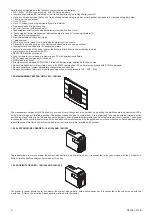
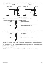
Inputs and tamper line can be configured as normally closed (NC) or balanced (single balancing). For balanced lines are used 2,7kohm resistors,
tolerance 1% (provided).
Ln
+V
2k7
+
AL
AL
CONTROL PANEL
DETECTOR
TA
TA
-
-V
To the tamper line
To the tamper line
-V
-
TA
TA
DETECTOR
CONTROL PANEL
AL
AL
+
+V
Ln
NC LINE
SINGLE
BALANCED LINE
Figure 22 – Inputs connection diagrams
The.balanced.connection.allows.to.detect.short.circuits.attempts.on.the.detectors.lines,.causing.an.alarm.
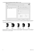
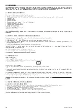
The.selection.of.connection.mode.is.made.with.the.jumper.JP1.on.the.motherboard.
JP1 closed
JP1 open
Lines and SAB input balanced
Lines and SAB input normally closed (NC)
(factory configuration)
WARNING
:.
The configuration is valid for all the lines; it is not possible to have some inputs or the tamper line configured as balanced and other
ones normally closed.
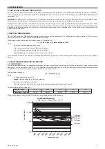
It is also possible to configure the inputs, except tamper input, in self by-pass mode with the motherboard jumper JP2.
JP2 closed
JP2 open
Self by-pass enabled
Self by-pass disabled (factory configuration)
WARNING
:.
Self by-pass activation is valid for all the inputs; it is not possible to have some inputs configured for self by-pass and other ones not
configured.
.
With self by-pass enabled, all the inputs that are open during the alarm system activation are automatically excluded, without generating an
alarm.signalling..If,.after.the.system.has.been.activated,.the.open.input.is.closed,.it.is.again.included.among.inputs.controlled.by.the.control.
panel,.and.an.alarm.is.generated.if.it.is.opened.again..
With self by-pass disabled, any input open when the system is activated generates an alarm.
WARNING
:.
Unused inputs must be connected to -RV with a wire, in case of NC lines, or with a 2K7 resistor, in case of balanced lines.
.


