DS1061-015B
13
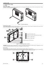
The electronic key reader and the proximity readers can be directly put on supports for flush mounting or wall mounting boxes of Simon Urmet
Nea residential series; they take up one module space. With specific adapters, present in catalogue, it is also possible to put them on flush
mounting.or.wall.mounting.boxes.of.the.most.common.residential.series.(BTicino.Living.International.and.Living,.Vimar.Plana.and.Idea,.Gewiss.
Playbus); also in this case, they take up one module space. Readers must be placed in a dry place, protected by bad weather conditions.
According to CEI 79.2 standards, the readers must be kept in self-protected housing (housings with anti-removal and anti-opening tamper). If
are used supports and plates of Simon Urmet Nea catalogue, a protection tamper (1069/416), designed for this purpose, is already available.
The.different.tampers.must.be.connected.in.series.
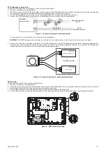
Nea plate
Nea adapter
Nea support
Reader
Ref. 1069/416
Figure 14 – Tamper for Simon Urmet Nea supports and plates
WARNING
:.
In order to connect to the control panel tamper line the tamper that protects the electronic key reader or the proximity reader, it is
necessary to lay a suitable line. So, if readers are installed, it is suggested to use for the bus a 6-wire cable and use 2 of them for the tamper
line.
3.3 MANAGEMENT KEYPAD
The management keypad can be placed both in a 3-modules flush mounting box (type 503) and in the provided wall mounting box. The keypad
must.be.placed.indoor,.in.a.zone.protected.by.the.alarm.system.
The.keypad.is.provided.with.the.following.screws:
no..3..
M.3,5.x..for.wall.mounting.with.screw.anchors.
No. 2
M 3,5 x 19 for frame fixing on box Mod. 503
.
No. 2
M 3,5 x 10 for fixing on wall mounting box
.
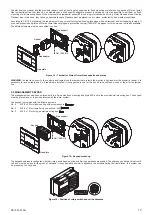
Nea plate
Keypad
Nea support
Ref. 1069/416
Figure 15 – Keypad mounting
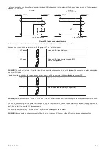
The keypads address is configured with their rotary switch and no other confirming operations are needed. The address can have a value from 0
to 3 and must be unique for the group of keypads. It is suggested to number in sequence the keypads during their installation. In a system can
be.present.up.to.4.keypads.
Figure 16 – Position of rotary switch and valid addresses

