


DS1061-015B
15
4. CONNECTIONS
WARNING
:.
All the connections must be performed when the system is unpowered. Connections providing power supply, mains and backup
battery must be performed as last operation!
Do.not.weld.the.end.of.a.stranded.conductor.in.the.points.where.the.wire.is.subject.to.a.contact.pressure..
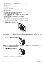
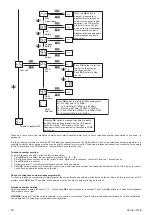
4.1 BUS DEVICES CONNECTION
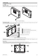
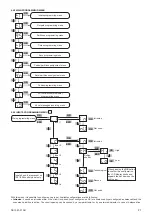
Connect.readers.and.keypads.to.the.control.panel.with.the.4-wire.bus..The.devices.must.be.daisy.chained.to.the.bus..The.order.used.to.connect.
the devices (management keypads, electronic key readers, proximity readers) to the bus is not relevant. The bus total length (that is the sum of
the single sections), according to cable dimensioning, must not exceed 500m.
Electronic key
reader
Proximity
reader
Keypad
12 3 A
B
C
D
0OK
9
85 6
47
X
Figure 19 – Devices connection to the bus
In all the devices, the bus terminal pins are identified as follows:
LA
Bus.line,.data
LB
Bus.line,.clock
+
Power.supply.1V,.positive
-
Power.supply.1V,.negative
WARNING
:.
If in the system are installed electronic key readers or proximity readers, it is suggested to use for the bus a 6-wire cable. So, besides
the 4 wire for bus, 2 wires will be available for the readers tamper line.
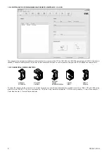
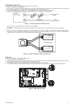
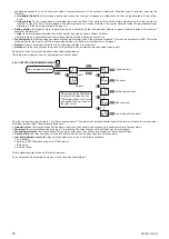
If.the.bus.line.length.exceeds.100m.and.there.are.only..devices.connected,.it.is.necessary.to.connect,.between.the.terminal.pins.“LA”.and.“–”.
and between “LB” and “–” of the two devices, 2,7kOhm resistors (the same used for input balancing).
-
LB
LA
+
2k7 2k7
2k7 2k7
+
LA
LB
-
CONTROL PANEL
DEVICE
(for ex. keypad)
BUS > 100 m
Figure 20 – Connection with length >100m between 2 devices
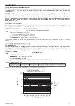
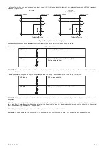
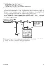
4.2 CONTROL PANEL
4.2.1 MOTHERBOARD
I
H
A
B
C
G
F
L
E
D
C
+
-
LA
LB
+
-
-V
+V
L1
L2
L3
L4
-V
+V
-
SAB
-
S
+SR
-
+SA
SIR
-
L5
-V
L6
- TMP
NO2
C2
NC2
NO1
C1
NC1
-BT
+BT
Figure 21 – Control panel motherboard