1
DS1061-015B
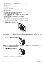
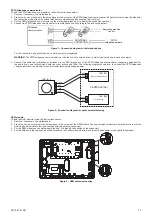
5... Screw.the.antenna.connector.to.the.SMA.connector.on.the.GSM.module..
.
WARNING
:.
Screw the connector by hand, without tools, in order not to damage it.
.
Figure 10 – GSM antenna connection
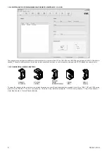
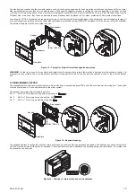
6... Release.the.SIM.holder.by.pressing.the.little.button.nearby,.and.open.it..
Figure 11 – SIM holder opening
7... Put.the.SIM.in.the.holder,.taking.care.contacts.are.visible,.and.close.again.the.holder..
WARNING
: If necessary for the SIM and/or for the mobile network carrier, use a mobile to enable the SIM and disable its PIN before inserting
the SIM in the GSM module.
Speech synthesis card
.
To.add.the.speech.synthesis.card,.follow.the.instructions.below:.
1.. Remove,.if.necessary,.the.motherboard.
.. Press.the.3.nylon.pivot.pins.in.the.holes.present.on.the.speech.synthesis.card..The.support.pivot.pins.must.be.placed.at.the.rear.of.the.
module (the side without electronic components and terminal strip).
3. Put the speech synthesis card on the motherboard (see fig. 6 to identify the position of the connector).
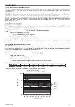
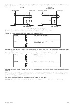
4. Connect the audio line (loudspeaker), if present, to the SPK terminal pin of the speech synthesis card, respecting polarities. For the audio
line,.use.a.twisted.pair..Audio.line.must.not.exceed.100m..The.following.diagram.shows.how.to.connect.the.speech.synthesis.card.and.the.
module.for.environmental.listening/messages.repeater.
1061/013
+SPK
+SPK
-SPK
-SPK
+MIC
+MIC
-MIC
-MIC
SPEECH SYNTHESIS CARD
1061/012
PSTN DIALLER
1061/002
CENTRALE 1061
Figure 12 – Connection diagram for messages repeater loudspeaker
3.2 ELECTRONIC KEY READER AND PROXIMITY READER
.
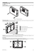
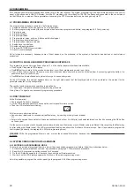
The address of electronic key readers and proximity readers is configured with their rotary switch and no confirmation operations are needed.
The.address.can.have.a.value.from.0.to.3.and.must be unique for the group of electronic key readers and proximity readers..It.is.suggested.to.
number in sequence the readers during their installation. In a system can be present up to 4 readers. For greater convenience, the addressing
operation.must.be.done.before.all.the.other.readers.install.operations..
Figure 13 – Position of rotary switch and valid addresses

