


69
Outdoor air management functions can be enhanced with
field-installation of these accessory control devices:
Enthalpy control (outdoor air or differential sensors)
Space CO
2
sensor
Outdoor air CO
2
sensor
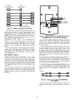
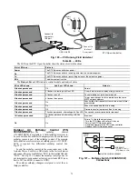
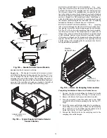
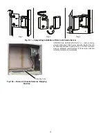
Field Connections —
Field connections for accessory
sensors and input devices are made the RTU Open controller, at
plugs J1, J2, J4, J5, J11 and J20. All field control wiring that
connects to the RTU Open controller must be routed through
the raceway built into the corner post as shown in Fig. 36. The
raceway provides the UL required clearance between high and
low-voltage wiring. Pass the control wires through the hole
provided in the corner post, then feed the wires through the
raceway to the RTU Open controller. Connect to the wires to
the removable Phoenix connectors and then reconnect the con-
nectors to the board.
SPACE TEMPERATURE (SPT) SENSORS — There are
two types of SPT sensors available from Carrier, resistive input
non-communicating (T-55, T-56, and T-59) and Rnet commu-
nicating (SPS, SPPL, SPP, and SPPF) sensors. Each type has a
variety of options consisting of: timed override button, set
point adjustment, a LCD screen, and communication tie in.
Space temperature can be also be written to from a building
network or zoning system. However, it is still recommended
that return air duct sensor be installed to allow stand-alone op-
eration for back-up. Refer to the configuration section for de-
tails on controller configurations associated with space sensors.
• 33ZCT55SPT, space temperature sensor with override
button (T-55)
• 33ZCT56SPT, space temperature sensor with override
button and setpoint adjustment (T-56)
• 33ZCT59SPT, space temperature sensor with LCD (liq-
uid crystal display) screen, override button, and setpoint
adjustment (T-59)
Use 20 gauge wire to connect the sensor to the controller.
The wire is suitable for distances of up to 500 ft. Use a three-
conductor shielded cable for the sensor and setpoint adjustment
connections. If the setpoint adjustment (slidebar) is not re-
quired, then an unshielded, 18 or 20 gauge, two-conductor,
twisted pair cable may be used.
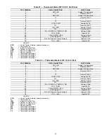
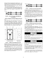
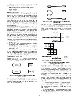
Connect T-55
—
See Fig. 77 for typical T-55 internal connec-
tions. Connect the T-55 SEN terminals to the RTU Open con-
troller at J20-1 and J20-2. See Fig. 110.
Fig. 110 — RTU Open Controller T-55 Sensor
Connections
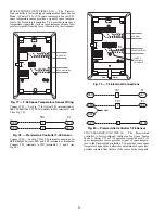
Connect T-56
—
See Fig. 79 for T-56 internal connections. In-
stall a jumper between SEN and SET terminals as illustrated.
Connect T-56 terminals to the RTU Open controller at J20
—
1,
J20
—
2 and J20
—
3 per Fig. 111.
Fig. 111 — RTU Open Controller T-56 Sensor
Connections
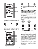
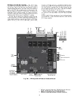
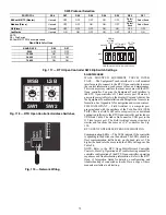
Connect T-59
—
The T-59 space sensor requires a separate,
isolated power supply of 24 VAC. See Fig. 112 for internal
connections at the T-59. Connect the SEN terminal (BLU) to
the RTU Open controller at J20
—
1. Connect the COM terminal
(BRN) to J20
—
2. Connect the SET terminal (STO or BLK) to
J20
—
3.
Fig. 112 — Space Temperature Sensor Typical
Wiring (33ZCT59SPT)
INDOOR AIR QUALITY (CO
2
) SENSOR — The indoor
air quality sensor accessory monitors space carbon dioxide
(CO
2
) levels. This information is used to monitor IAQ levels.
Several types of sensors are available, for wall mounting in the
space or in return duct, with and without LCD display, and in
combination with space temperature sensors. Sensors use infra-
red technology to measure the levels of CO
2
present in the
space air.
The CO
2
sensors are all factory set for a range of 0 to 2000
ppm and a linear mA output of 4 to 20. Refer to the instructions
supplied with the CO
2
sensor for electrical requirements and
terminal locations. See Fig. 87 for typical CO
2
sensor wiring
schematic.
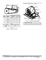
To accurately monitor the quality of the air in the condi-
tioned air space, locate the sensor near a return-air grille (if
present) so it senses the concentration of CO
2
leaving the space.
The sensor should be mounted in a location to avoid direct
breath contact.
Do not mount the IAQ sensor in drafty areas such as near
supply ducts, open windows, fans, or over heat sources. Allow
at least 3 ft (0.9 m) between the sensor and any corner. Avoid
S
EN
S
EN
J20-1
J20-2
S
EN
J20-1
J20-2
S
EN
S
ET
J
u
mper
J20-
3
S
ET
OR
SET
SEN
OPB
COM- PWR+
BLU (SPT)
BLK (STO)
24 VAC
SENSOR
WIRING
POWER
WIRING
BRN (COM)
NOTE: Must use a separate isolated transformer.
J20-3
J20-2
J20-1
Summary of Contents for Carrier WeatherMaker 50TC A08 Series
Page 4: ...4 Fig 2 Unit Dimensional Drawing Size 08 09 12 Units...
Page 5: ...5 Fig 2 Unit Dimensional Drawing Size 08 09 12 Units cont...
Page 6: ...6 Fig 3 Unit Dimensional Drawing Size 14 Unit...
Page 7: ...7 Fig 3 Unit Dimensional Drawing Size 14 Unit cont...
Page 9: ...9 Fig 4 Unit Dimensional Drawing Size 16 Unit cont...
Page 13: ...13 Fig 8 Roof Curb Details Size 16 Unit...
Page 50: ...50 Fig 73 50TC 16 Control Box Component PremierLink Locations...
Page 51: ...51 Fig 74 Typical PremierLink Control Wiring Diagram...
Page 52: ...52 Fig 75 Typical PremierLink Control Wiring Diagram with Humidi MiZer System Option...
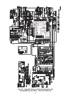
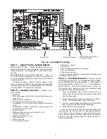
Page 64: ...64 Fig 106 Typical RTU Open Controller Wiring Diagram 50TC 08 14 Size Units...
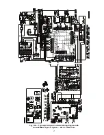
Page 65: ...65 Fig 107 Typical RTU Open Controller Wiring Diagram 50TC 16 Size Unit...


