


14
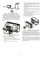
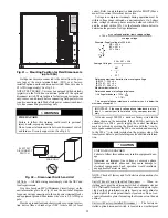
ALTERNATE UNIT SUPPORT (IN LIEU OF CURB OR
SLAB MOUNT) — A non-combustible sleeper rail can be
used in the unit curb support area. If sleeper rails cannot be
used, support the long sides of the unit with a minimum of 3
equally spaced 4-in. x 4-in. (102 mm x 102 mm) pads on each
side.
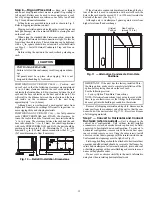
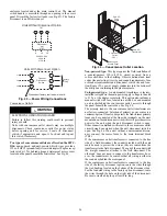
Step 5 — Field Fabricate Ductwork —
Cabinet
return-air static pressure (a negative condition) shall not exceed
0.35 in. wg (87 Pa) with economizer or 0.45 in. wg (112 Pa)
without economizer.
For vertical ducted applications, secure all ducts to roof curb
and building structure.
Do not connect ductwork to unit.
Fabricate supply ductwork so that the cross sectional di-
mensions are equal to or greater than the unit supply duct open-
ing dimensions for the first 18 in. (458 mm) of duct length
from the unit basepan.
Insulate and weatherproof all external ductwork, joints, and
roof openings with counter flashing and mastic in accordance
with applicable codes.
Ducts passing through unconditioned spaces must be insu-
lated and covered with a vapor barrier.
If a plenum return is used on a vertical unit, the return
should be ducted through the roof deck to comply with applica-
ble fire codes.
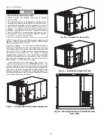
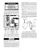
FOR UNITS WITH ACCESSORY ELECTRIC HEAT-
ERS — All installations require a minimum clearance to com-
bustible surfaces of 1-in. (25 mm) from duct for first 12-in.
(305 mm) away from unit.
Outlet grilles must not lie directly below unit discharge.
NOTE: A 90-degree elbow must be provided in the ductwork
to comply with UL (Underwriters Laboratories) code for use
with electric heat.
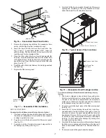
Before setting the unit onto the curb, recheck gasketing on
the curb.
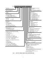
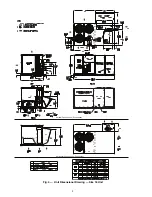
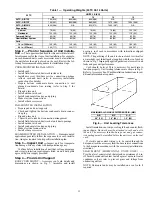
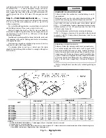
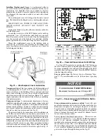
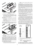
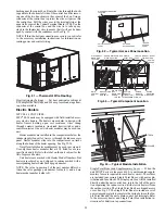
Fig. 9 — Rigging Details
CAUTION
PROPERTY DAMAGE HAZARD
Failure to follow this caution may result in damage to roof-
ing materials.
Membrane roofs can be cut by sharp sheet metal edges. Be
careful when placing any sheet metal parts on such roof.
CAUTION
PERSONAL INJURY HAZARD
Failure to follow this warning could cause personal injury.
For vertical supply and return units, tools or parts could
drop into ductwork and cause an injury. Install a 90-degree
turn in the return ductwork between the unit and the condi-
tioned space. If a 90-degree elbow cannot be installed, then
a grille of sufficient strength and density should be installed
to prevent objects from falling into the conditioned space.
Due to electric heater, supply duct will require 90-degree
elbow.
NOTES:
1. SPREADER BARS REQUIRED — Top damage will occur if spreader bars are not used.
2. Dimensions in ( ) are in millimeters.
3. Hook rigging shackles through holes in base rail, as shown in detail “A.” Holes in base rails are centered around the unit center of gravity.
Use wooden top to prevent rigging straps from damaging unit.
UNIT
MAX WEIGHT
DIMENSIONS
A
B
C
lb
kg
in.
mm
in.
mm
in.
mm
50TC-A08
1290
586
88.0
2235
40.0
1015
41,5
1055
50TC-A09
1410
641
88.0
2235
39.5
1005
49.5
1255
50TC-A12
1515
689
88.0
2235
41,0
1040
49,5
1255
50TC-D/E08
1410
641
88,0
2235
41.0
1040
41.5
1055
50TC-D/E09
1525
693
88.0
2235
40.5
1030
49,5
1255
50TC-D/E12
1565
711
88,0
2235
40,0
1015
49,5
1255
50TC-D/E14
1720
782
88.0
2235
28,5
725
53,0
1345
50TC-D16
912
2010
2945
116.0
1461
57.5
1510
59.5
Summary of Contents for Carrier WeatherMaker 50TC A08 Series
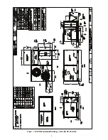
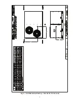
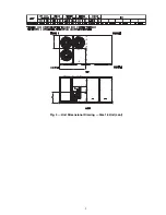
Page 4: ...4 Fig 2 Unit Dimensional Drawing Size 08 09 12 Units...
Page 5: ...5 Fig 2 Unit Dimensional Drawing Size 08 09 12 Units cont...
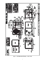
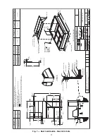
Page 6: ...6 Fig 3 Unit Dimensional Drawing Size 14 Unit...
Page 7: ...7 Fig 3 Unit Dimensional Drawing Size 14 Unit cont...
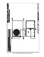
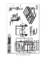
Page 9: ...9 Fig 4 Unit Dimensional Drawing Size 16 Unit cont...
Page 13: ...13 Fig 8 Roof Curb Details Size 16 Unit...
Page 50: ...50 Fig 73 50TC 16 Control Box Component PremierLink Locations...
Page 51: ...51 Fig 74 Typical PremierLink Control Wiring Diagram...
Page 52: ...52 Fig 75 Typical PremierLink Control Wiring Diagram with Humidi MiZer System Option...
Page 64: ...64 Fig 106 Typical RTU Open Controller Wiring Diagram 50TC 08 14 Size Units...
Page 65: ...65 Fig 107 Typical RTU Open Controller Wiring Diagram 50TC 16 Size Unit...


