


71
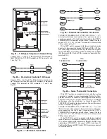
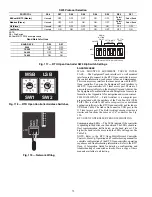
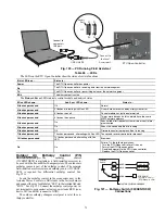
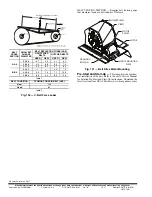
Fig. 116 — Duct Relative Humidity Sensor Typical
Wiring
Humidistat
—
The accessory humidistat provides the RTU
Open controller insight to the relative humidity in the space.
The humidistat reads the RH level in the space and compares it
to its setpoint to operate a dry contact. The humidistat is a dedi-
cated input on the configurable input 9 and tells the RTU Open
controller when the RH level is HIGH or LOW. The normal
condition for humidity is LOW. A normally open humidistat is
the factory default control for the Humidi-MiZer System op-
tion.
To wire in the field:
• J5
—
8 = 24 VAC source for dry contact
• J5
—
7 = Signal input
SMOKE DETECTOR/FIRE SHUTDOWN (FSD) — On
50TC units equipped with factory-installed Smoke Detector(s),
the smoke detector controller implements the unit shutdown
through its NC contact set connected to the unit’s CTB input.
The FSD function is initiated via the smoke detector’s Alarm
NO contact set. The RTU Open controller communicates the
smoke detector’s tripped status to the BAS building control.
See Fig. 106 and 108, (RTU Open Controller wiring diagrams).
The Fire Shutdown Switch configuration,
MENU
Con-
fig
Inputs
input 5
, identifies the normally open status of
this input when there is no fire alarm.
CONNECTING DISCRETE INPUTS — Filter Status: The
filter status accessory is a field-installed accessory. This acces-
sory detects plugged filters. When installing this accessory, the
unit must be configured for filter status by setting
MENU
Config
Inputs
input 3, 5, 8, or 9
to Filter Status
and normally open (N/O) or normally closed (N/C). Input 8 or
9 is recommended for ease of installation. Refer to Fig. 105-
109 for wire terminations at J5.
Fan Status
—
The fan status accessory is a field-installed ac-
cessory. This accessory detects when the indoor fan is blowing
air. When installing this accessory, the unit must be configured
for fan status by setting
MENU
Config
Inputs
input 3,
5, 8, or 9
to Fan Status and normally open (N/O) or normally
closed (N/C). Input 8 or 9 is recommended for easy of installa-
tion. Refer to Fig. 105-109 for wire terminations at J5.
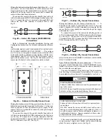
Remote Occupancy
—
The remote occupancy accessory is a
field-installed accessory. This accessory overrides the unoccu-
pied mode and puts the unit in occupied mode. When installing
this accessory, the unit must be configured for remote occupan-
cy by setting
MENU
Config
Inputs
input 3, 5, 8, or 9
to
Remote Occupancy and normally open (N/O) or normally
closed (N/C).
Also set
MENU
Schedules
occupancy source
to DI on/
off. Input 8 or 9 is recommended for ease of installation. Refer
to Fig. 105 and Table 25 for wire terminations at J5.
Power Exhaust (output)
—
The relay used by the RTU Open
controller board to control power exhaust is a dry contact
which means it does not have 24vac. This 24vac must be con-
nected to the relay to allow it to operate the power exhaust re-
lay in the PE accessory. A 24vac source must be provided to
J11
—
2 on the RTU Open controller board. This can be provid-
ed by the unit’s transformer from various sources. The “R” ter-
minal on the unit’s central terminal board (CTB) is a logical
source. Refer to Fig. 105-109 for wire terminations at J11.
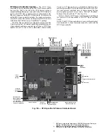
Communication Wiring
—
Protocols
GENERAL — Protocols are the communication languages
spoken by control devices. The main purpose of a protocol is to
communicate information in the most efficient method possi-
ble. Different protocols exist to provide different kinds of infor-
mation for different applications. In the BAS application, many
different protocols are used, depending on manufacturer. Proto-
cols do not change the function of a controller; just make the
front end user different.
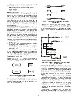
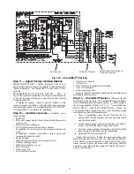
The RTU Open controller can be set to communicate on
four different protocols: BACnet, Modbus, N2, and LonWorks.
Switch 3 (SW3) on the board is used to set protocol and baud
rate. Switches 1 and 2 (SW1 and SW2) are used to set the
board’s network address. See Fig. 117 and 118 for protocol
switch settings and address switches. The third party connec-
tion to the RTU Open controller is through plug J19. See
Fig. 119 for wiring.
NOTE: Power must be cycled after changing the SW1
—
3
switch settings.
Refer to the RTU Open Controller Integration Guide for
more detailed information on protocols, third party wiring, and
networking.
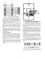
SPAN
ZERO
4-20
mA
VAC
or
VDC
GND 0-5V
or
0-10V
1
2
3
4
5
6
ON
J4-1 or J4-4 + 24 VDC
SUPPLY VOLTAGE
J4-2 or J4-5 (-)4 to 20 mA Current
LOOP OUTPUT TO RTU OPEN
RELATIVE HUMIDITY SENSOR
(POLARIZED MALE CONNECTOR)
Summary of Contents for Carrier WeatherMaker 50TC A08 Series
Page 4: ...4 Fig 2 Unit Dimensional Drawing Size 08 09 12 Units...
Page 5: ...5 Fig 2 Unit Dimensional Drawing Size 08 09 12 Units cont...
Page 6: ...6 Fig 3 Unit Dimensional Drawing Size 14 Unit...
Page 7: ...7 Fig 3 Unit Dimensional Drawing Size 14 Unit cont...
Page 9: ...9 Fig 4 Unit Dimensional Drawing Size 16 Unit cont...
Page 13: ...13 Fig 8 Roof Curb Details Size 16 Unit...
Page 50: ...50 Fig 73 50TC 16 Control Box Component PremierLink Locations...
Page 51: ...51 Fig 74 Typical PremierLink Control Wiring Diagram...
Page 52: ...52 Fig 75 Typical PremierLink Control Wiring Diagram with Humidi MiZer System Option...
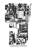
Page 64: ...64 Fig 106 Typical RTU Open Controller Wiring Diagram 50TC 08 14 Size Units...
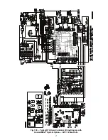
Page 65: ...65 Fig 107 Typical RTU Open Controller Wiring Diagram 50TC 16 Size Unit...


