


3
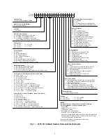
Fig. 1 — 50TC 08-16 Model Number Nomenclature (Example)
Model Series - WeatherMaker
®
TC - Standard Efficiency
Unit Heat Type
50 - Electric Heat Packaged Rooftop
Cooling Tons
08 = 7.5 tons
14 = 12.5 tons
09 = 8.5 tons
16 = 15 tons
12 = 10 tons
Heat Size
- = No heat
Sensor Options
A = None
B = RA Smoke Detector
C = SA Smoke Detector
D = RA + SA Smoke Detector
E = CO
2
Sensor
F = RA Smoke Detector and CO
2
Sensor
G = SA Smoke Detector and CO
2
Sensor
H = RA + SA Smoke Detector and CO
2
Sensor
Indoor Fan Options
1 = Belt Drive, Standard Static Option
2 = Belt Drive, Medium Static Option
3 = Belt Drive, High Static Option
C = High Static Option with High Efficiency Motor (Size 16 Only)
Refrig. Systems Options
A = Standard One Stage Cooling Models
D = Two Stage Cooling Models 08-16
E = Two Stage Cooling Models 08-16 with
Al/Cu condenser Coils and with Humidi-MiZer
Coil Options – RTPF (Outdoor - Indoor - Hail Guard)
A = Al/Cu - Al/Cu
B = Precoat Al/Cu - Al/Cu
C = E-coat Al/Cu - Al/Cu
D = E-coat Al/Cu - E-coat Al/Cu
E = Cu/Cu - Al/Cu
F = Cu/Cu - Cu/Cu
M = Al/Cu -Al/Cu — Louvered Hail Guard
N = Precoat Al/Cu - Al/Cu — Louvered Hail Guard
P = E-coat Al/Cu - Al/Cu — Louvered Hail Guard
Q = E-coat Al/Cu - E-coat Al/Cu — Louvered Hail Guard
R = Cu/Cu - Al/Cu — Louvered Hail Guard
S = Cu/Cu - Cu/Cu — Louvered Hail Guard
Coil Options – Novation
®
(Outdoor - Indoor - Hail Guard)
G = Al/Al - Al/Cu
H = Al/Al - Cu/Cu
J = Al/Al - E-coat Al/Cu
K = E-coat Al/Al - Al/Cu
L = E-coat Al/Al - E-coatAl/Cu
T = Al/Al - Al/Cu — Louvered Hail Guard
U = Al/Al - Cu/Cu — Louvered Hail Guard
V = Al/Al - E-coat Al/Cu — Louvered Hail Guard
W = E-coat Al/Al - Al/Cu — Louvered Hail Guard
X = E-coat Al/Al - E-coat Al/Cu — Louvered Hail Guard
Design Revision
- = Factory Design Revision
Base Unit Controls
0 = Electromechanical Controls can be used with W7212
EconoMi$er IV (Non-Fault Detection and Diagnostic)
1 = PremierLink Controller
2 = RTU Open Multi-Protocol Controller
6 = Electro-mechanical w/ 2-Speed Fan and W7220
Economizer Controller Controls. Can be used with
W7220 EconoMi$er X (w/ Fault Detection & Diagnostic)
Intake / Exhaust Options
A = None
B = Temperature Economizer w/ Barometric Relief
F = Enthalpy Economizer w/ Barometric Relief
K = 2-Position Damper
U = Temperature Ultra Low Leak Economizer
w/ Barometric Relief
W = Enthalpy Ultra Low Leak Economizer
w/ Barometric Relief
Service Options
0 = None
1 = Unpowered Convenience Outlet
2 = Powered Convenience Outlet
3 = Hinged Panels
4 = Hinged Panels and
Unpowered Convenience Outlet
5 = Hinged Panels and
Powered Convenience Outlet
Packaging & Seismic Compliance
0 = Standard
1 = LTL
3 = California Seismic Compliant Label
4 = LTL and CA Seismic Compliant Label
Electrical Options
A = None
C = Non-Fused Disconnect
D = Thru-The-Base Connections
F = Non-Fused Disconnect and
Thru-The-Base
Connections
G = 2-Speed Indoor Fan (VFD) Controller
J = 2 Speed Fan Controller (VFD) and
Non-Fused
Disconnect
K = 2 Speed Fan Controller (VFD) and
Thru-The-Base
Connections
M = 2 Speed Fan Controller (VFD)
with Non-Fused Disconnect and
Thru-The-Base
Connections
Example:
Position:
5
0
T
C
-
A
0
4
A
1
A
5
-
0
A
0
A
0
1
2
3
4
5
6
7
8
9
10 11 12 13 14 15 16 17 18
Voltage
1 = 575/3/60
5 = 208-230/3/60
3 = 208-230/1/60
1
6 = 460/3/60
NOTES:
On single phase (-3 voltage code) models, the following
are not available as a factory installed option:
- Humidi-MiZer
- Coated Coils or Cu Fin Coils
- Louvered Hail Guards
- Economizer or 2 Position Damper
- Powered 115 Volt Convenience Outlet
1
Production of single phase voltage models has been discontinued per
DOE regulations. Single phase 50TC models will only be available
until current inventories are exhausted.
Not all possible options are displayed, see the current
Price Pages for more details.
Summary of Contents for Carrier WeatherMaker 50TC A08 Series
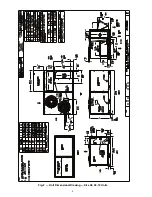
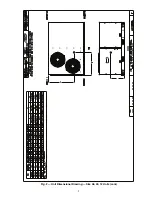
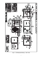
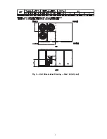
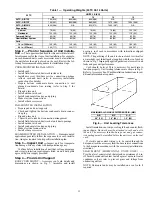
Page 4: ...4 Fig 2 Unit Dimensional Drawing Size 08 09 12 Units...
Page 5: ...5 Fig 2 Unit Dimensional Drawing Size 08 09 12 Units cont...
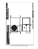
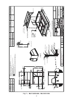
Page 6: ...6 Fig 3 Unit Dimensional Drawing Size 14 Unit...
Page 7: ...7 Fig 3 Unit Dimensional Drawing Size 14 Unit cont...
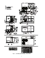
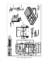
Page 9: ...9 Fig 4 Unit Dimensional Drawing Size 16 Unit cont...
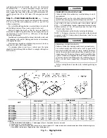
Page 13: ...13 Fig 8 Roof Curb Details Size 16 Unit...
Page 50: ...50 Fig 73 50TC 16 Control Box Component PremierLink Locations...
Page 51: ...51 Fig 74 Typical PremierLink Control Wiring Diagram...
Page 52: ...52 Fig 75 Typical PremierLink Control Wiring Diagram with Humidi MiZer System Option...
Page 64: ...64 Fig 106 Typical RTU Open Controller Wiring Diagram 50TC 08 14 Size Units...
Page 65: ...65 Fig 107 Typical RTU Open Controller Wiring Diagram 50TC 16 Size Unit...


