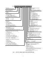


10
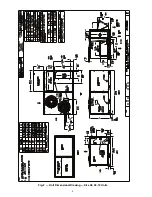
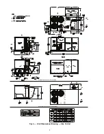
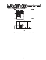
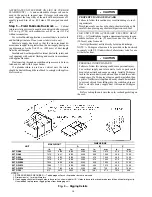
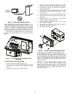
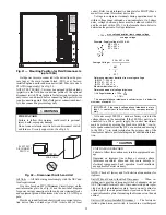
Fig. 5 — Service Clearance Dimensional Drawing
INSTALLATION
Jobsite Survey —
Complete the following checks before
installation.
1. Consult local building codes and the NEC (National
Electrical Code) ANSI/NFPA 70 for special installation
requirements.
2. Determine unit location (from project plans) or select unit
location.
3. Check for possible overhead obstructions which may in-
terfere with unit lifting or rigging.
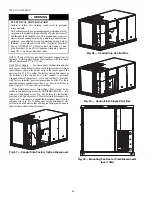
Step 1 — Plan for Unit Location —
Select a loca-
tion for the unit and its support system (curb or other) that pro-
vides for the minimum clearances required for safety. This in-
cludes the clearance to combustible surfaces, unit performance
and service access below, around and above unit as specified in
unit drawings. See Fig. 7.
NOTE: Consider also the effect of adjacent units.
Unit may be installed directly on wood flooring or on Class
A, B, or C roof-covering material when roof curb is used. Do
not install unit in an indoor location. Do not locate air inlets
near exhaust vents or other sources of contaminated air.
Although unit is weatherproof, avoid locations that permit
water from higher level runoff and overhangs to fall onto the
unit.
Select a unit mounting system that provides adequate height
to allow for removal and disposal of frost and ice that will form
during the heating-defrost mode as well as allow installation of
condensate trap per requirements. Refer to Step 9 — Install Ex-
ternal Condensate Trap and Line – for required trap dimen-
sions.
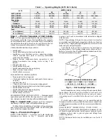
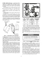
ROOF MOUNT — Check building codes for weight distri-
bution requirements. Unit operating weight is shown in
Table 1.
NOTE: Unit not designed to have overhead obstruction. Contact Application Engineering for guidance on any application planning overhead
obstruction or for vertical clearances.
LOCATION
DIMENSION
CONDITION
A
48-in. (1219 mm)
18-in. (457 mm)
18-in. (457) mm
12-in. (305 mm)
Unit disconnect is mounted on panel
No disconnect, convenience outlet option
Recommended service clearance
Minimum clearance
B
42-in. (1067 mm)
36-in. (914 mm)
Special
Surface behind servicer is grounded (e.g., metal, masonry wall)
Surface behind servicer is electrically non-conductive (e.g., wood, fiberglass)
Check sources of flue products within 10-ft of unit fresh air intake hood
C
36-in. (914 mm)
18-in. (457 mm)
Side condensate drain is used
Minimum clearance
D
48 in. (1219 mm)
42-in. (1067 mm)
36-in. (914 mm)
Special
No flue discharge accessory installed, surface is combustible material
Surface behind servicer is grounded (e.g., metal, masonry wall, another unit)
Surface behind servicer is electrically non-conductive (e.g., wood, fiberglass)
Check for adjustable units or building fresh air intakes within 10 ft (3 m) of this units flue outlet
C
B
A
D
Summary of Contents for Carrier WeatherMaker 50TC A08 Series
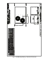
Page 4: ...4 Fig 2 Unit Dimensional Drawing Size 08 09 12 Units...
Page 5: ...5 Fig 2 Unit Dimensional Drawing Size 08 09 12 Units cont...
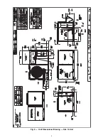
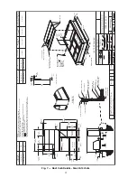
Page 6: ...6 Fig 3 Unit Dimensional Drawing Size 14 Unit...
Page 7: ...7 Fig 3 Unit Dimensional Drawing Size 14 Unit cont...
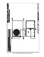
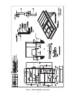
Page 9: ...9 Fig 4 Unit Dimensional Drawing Size 16 Unit cont...
Page 13: ...13 Fig 8 Roof Curb Details Size 16 Unit...
Page 50: ...50 Fig 73 50TC 16 Control Box Component PremierLink Locations...
Page 51: ...51 Fig 74 Typical PremierLink Control Wiring Diagram...
Page 52: ...52 Fig 75 Typical PremierLink Control Wiring Diagram with Humidi MiZer System Option...
Page 64: ...64 Fig 106 Typical RTU Open Controller Wiring Diagram 50TC 08 14 Size Units...
Page 65: ...65 Fig 107 Typical RTU Open Controller Wiring Diagram 50TC 16 Size Unit...


