


56
SPACE SENSORS (UNIT SIZES 08-14) — The Premier-
Link controller is factory-shipped configured for Space Sensor
Mode. A Carrier T-55 or T-56 space sensor must be used. T-55
space temperature sensor provides a signal of space tempera-
ture to the PremierLink controller. T-56 provides same space
temperature signal plus it allows for adjustment of space tem-
perature setpoints from the face of the sensor by the occupants.
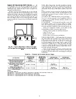
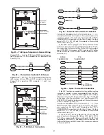
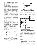
Fig. 77 — T-55 Space Temperature Sensor Wiring
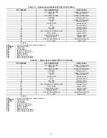
Connect T-55 — See Fig. 77 for typical T-55 internal connec-
tions. Connect the T-55 SEN terminals to TB1 terminals 1 and
3 (see Fig. 78).
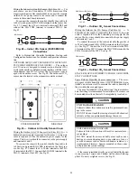
Fig. 78 — PremierLink Controller T-55 Sensor
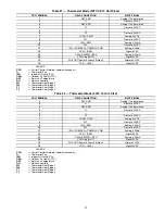
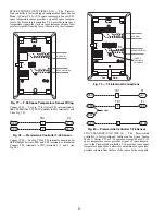
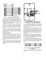
Connect T-56 — See Fig. 79 for T-56 internal connections. In-
stall a jumper between SEN and SET terminals as illustrated.
Connect T-56 terminals to TB1 terminals 1, 3 and 5 (see
Fig. 80).
Fig. 79 — T-56 Internal Connections
Fig. 80 — PremierLink Controller T-56 Sensor
SPACE SENSORS (UNIT SIZE 16) — The PremierLink
controller is factory-shipped configured for Space Sensor
Mode. A Carrier T-55 or T-56 space sensor must be used. T-55
space temperature sensor provides a signal of space tempera-
ture to the PremierLink controller. T-56 provides same space
temperature signal plus it allows for adjustment of space tem-
perature setpoints from the face of the sensor by the occupants.
2
3
4
5
6
1
S
W1
S
EN
BRN (GND)
BLU (
S
PT)
RED(+)
WHT(GND)
BLK(-)
CCN COM
S
EN
S
OR WIRING
SEN
J6-7
J6-6
1
3
TB1
PL
SEN
2
3
4
5
6
1
S
W1
S
EN
S
ET
Cool
Warm
BRN (GND)
BLU (
S
PT)
RED(+)
WHT(GND)
BLK(-)
CCN COM
S
EN
S
OR WIRING
JUMPER
TERMINAL
S
A
S
S
HOWN
BLK
(T56)
S
EN
J6-7
J6-6
1
3
TB1
PL
S
EN
S
ET
J
u
mper
TB1
PL
J6-5
5
S
ET
Summary of Contents for Carrier WeatherMaker 50TC A08 Series
Page 4: ...4 Fig 2 Unit Dimensional Drawing Size 08 09 12 Units...
Page 5: ...5 Fig 2 Unit Dimensional Drawing Size 08 09 12 Units cont...
Page 6: ...6 Fig 3 Unit Dimensional Drawing Size 14 Unit...
Page 7: ...7 Fig 3 Unit Dimensional Drawing Size 14 Unit cont...
Page 9: ...9 Fig 4 Unit Dimensional Drawing Size 16 Unit cont...
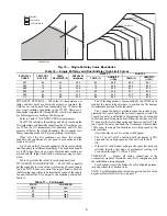
Page 13: ...13 Fig 8 Roof Curb Details Size 16 Unit...
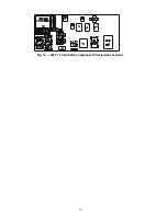
Page 50: ...50 Fig 73 50TC 16 Control Box Component PremierLink Locations...
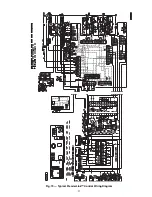
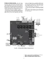
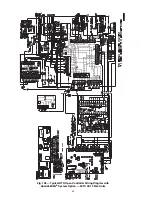
Page 51: ...51 Fig 74 Typical PremierLink Control Wiring Diagram...
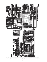
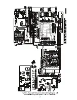
Page 52: ...52 Fig 75 Typical PremierLink Control Wiring Diagram with Humidi MiZer System Option...
Page 64: ...64 Fig 106 Typical RTU Open Controller Wiring Diagram 50TC 08 14 Size Units...
Page 65: ...65 Fig 107 Typical RTU Open Controller Wiring Diagram 50TC 16 Size Unit...


