


UNIBLOC-PD Operation & Service Manual: PD600-677 25
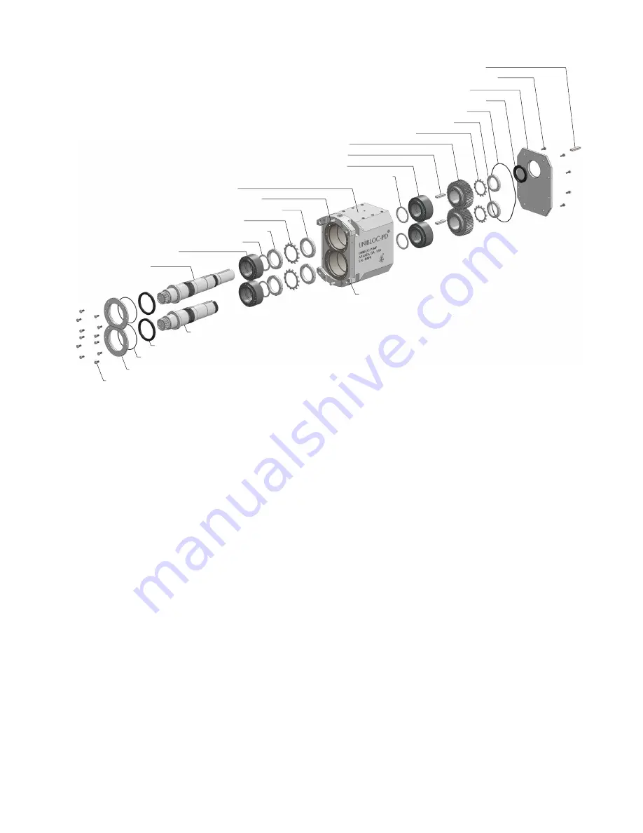
BOLTS
(FRONT BEARING RETAINER RINGS)
RETAINER RINGS
(FRONT BEARING)
DRIVE SHAFT
FRONT BEARINGS
SHOULDER RINGS
(FRONT BEARINGS)
SLOTTED NUTS
(FRONT BEARING RETAINING)
SLOTTED NUTS
(FRONT BEARING LOCKING)
TAB WASHERS
(FRONT BEARINGS)
DOWEL PINS
(BEARING HOUSING)
BEARING HOUSING
SHOULDER RINGS
(REAR BEARINGS)
REAR BEARINGS
GEAR KEYS
GEARS
TAB WASHERS
(GEARS)
SLOTTED NUTS
(GEAR LOCKING)
O-RING
(BEARING HOUSING COVER)
OIL SEAL
(BEARING HOUSING COVER)
COVER
(BEARING HOUSING)
BOLTS
(BEARING HOUSING COVER)
SHAFT KEY
(DRIVE SHAFT)
O-RINGS
(FRONT BEARING RETAINER RINGS)
OIL SEALS
(BEARING HOUSING)
LAY SHAFT
SHIMS
fig. 4.15
4.5 Bearing Housing Maintenance and Service
(reference fig. 4.15)
The UNIBLOC-PD bearing housing contains a single lubricating oil chamber. The oil level should be checked at
regular intervals and the oil should be changed once per year or after 2000 hours of operation, whichever occurs first.
When applications exceed constant service temperatures of 180
°
C (356
°
F) high temperature lubricants must be used.
For such cases, contact Unibloc-Pump or an authorized service center for a service schedule.
Before proceeding with the following steps,
DISENGAGE POWER TO THE MOTOR
. If the pump is connected to
piping,
depressurize the system and close valves on both the suction and discharge sides to isolate the pump
from the rest of the system.
Disconnect the piping and remove the pump from the system using eye bolts on both
the
Rotor Housing
and the
Bearing Housing
. Removal of the wet end of the pump (i.e. the cover, rotors, rotor hous
-
ing, and shaft seals) must be completed first before the bearing housing is dismantled. The method of removing these
parts is dependent upon the type of shaft seals the pump has and is outlined in section 4.4.
4.5.1 Bearing Housing Disassembly
(reference fig. 4.15)
Remove the front cover, rotors, housing and shaft seals as described in section 4. Drain oil from the
Bearing Hous-
ing
by removing the appropriate drain plug as shown in section 6.2. Remove the
Drive Shaft Key
and the
Bearing
Housing Cover
. Open the tab on the
Tab Washers (gears)
and remove them and the
Slotted Nuts (gear locking)
.
Remove the
Gears
using a gear puller and the M8 tapped holes on the gears. Remove the
Gear Keys
. The
Gears
can also be removed when pressing out the
Shafts
, but the
Gear Keys
will have to be removed simultaneously.
Unbolt and remove the
Retainer Rings (front bearing)
. Install the assembly plate (contact Unibloc-Pump for details)
on the
Dowel Pins (bearing housing)
and bolt to the
Bearing Housing
. Turn the pump so the
Drive Shaft
points
up. The plate will catch the shafts when they are pressed out. Pressing on the
Drive Shaft
end of the pump, use a hy
-
draulic press to remove the
Drive and Lay Shafts
. The
Front Bearings
will come out assembled to the
Shafts
. The
Gears
will also come out if not removed previously. Remove the assembly plate and shafts. Remove the
Slotted Nuts
(front bearing retaining)
and
Tab Washers (front bearing)
holding the
Front Bearings
. Do not fix the shaft such
that the shaft seal or oil seal areas are damaged. Press off the
Front Bearings
only if they need to be replaced. Slide
or press out the
Rear Bearings
using assembly
6190B
(see section 6.3.2). Each bearing set must remain together.