14
SECTION 3
CONSTRUCTION AND PRINCIPLE
3.1
Pump Construction
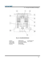
Fig. 3-1 is a sectional drawing of a turbo molecular pump. The built-in high frequency motor (1)
is accelerated to the specified revolutions (speed) by the high frequency power supply unit. Rotor
blades (3) are fitted onto the drive shaft (2) and the stator blades (4) are arranged in between the
rotor blades. A positioning spacer (5) is inserted between the stator blades. The configurations
and profiles of the stator blades and rotor blades are designed for high efficiencies in various
applications. The upper stages of the rotor blade and stator blade configurations are ideally
designed for high gas throughput. The compression ratio of the stator blades and rotor blades
becomes higher as the gas molecules converge into the lower stage configurations. The profiles
of the stator blades and rotor blades are matched for the desired function.
The shaft (2) is held with the permanent magnet (7) and the ball bearing (6).
A touch-down bearing (8) is used at the top of the casing for safety protection of rotor.
Protective net (11) protects that a foreign object comes in from inlet flange.
3.2
Principle of Turbo Molecular Pumping
The principle of turbo molecular pumping assumes gas molecules collide with a surface plane
(the blade of the pump rotor) moving in a radial span of very high speed in a space with an
enlarged mean free gas path (generally a vacuum area of less pressure than 0.1 Pa). Assuming
no heat is exchanged between the gas molecule and the pump rotor blade, the speed of the
pump rotor blade is added to the speed of the gas molecule, converting the gas molecule's
non-oriented thermal motion to a motion with direction. Thus the gas molecule has received an
impulse in a desired flow direction.
Summary of Contents for UTM300B
Page 8: ...vii Location of label...
Page 11: ...x This page is intentionally left blank...
Page 17: ...xvi Table of contents This page is intentionally left blank...
Page 51: ...34 SECTION 5 INSTALLATION This page is intentionally left blank...
Page 70: ...GAS PURGE 7...
Page 77: ...60 SECTION 8 TURBO MOLECULAR PUMP RECONDITION This page is intentionally left blank...
Page 111: ...A 26 Appendix A COMMUNICATIONS This page is intentionally left blank...

